EasyManuals Logo

Danfoss VLT series Service Manual

Danfoss VLT series
158 pages
To Next Page IconTo Next Page
To Previous Page IconTo Previous Page
Page #89 background imageLoading...
Page #89 background image
5-23
VLT is a registered Danfoss trademark
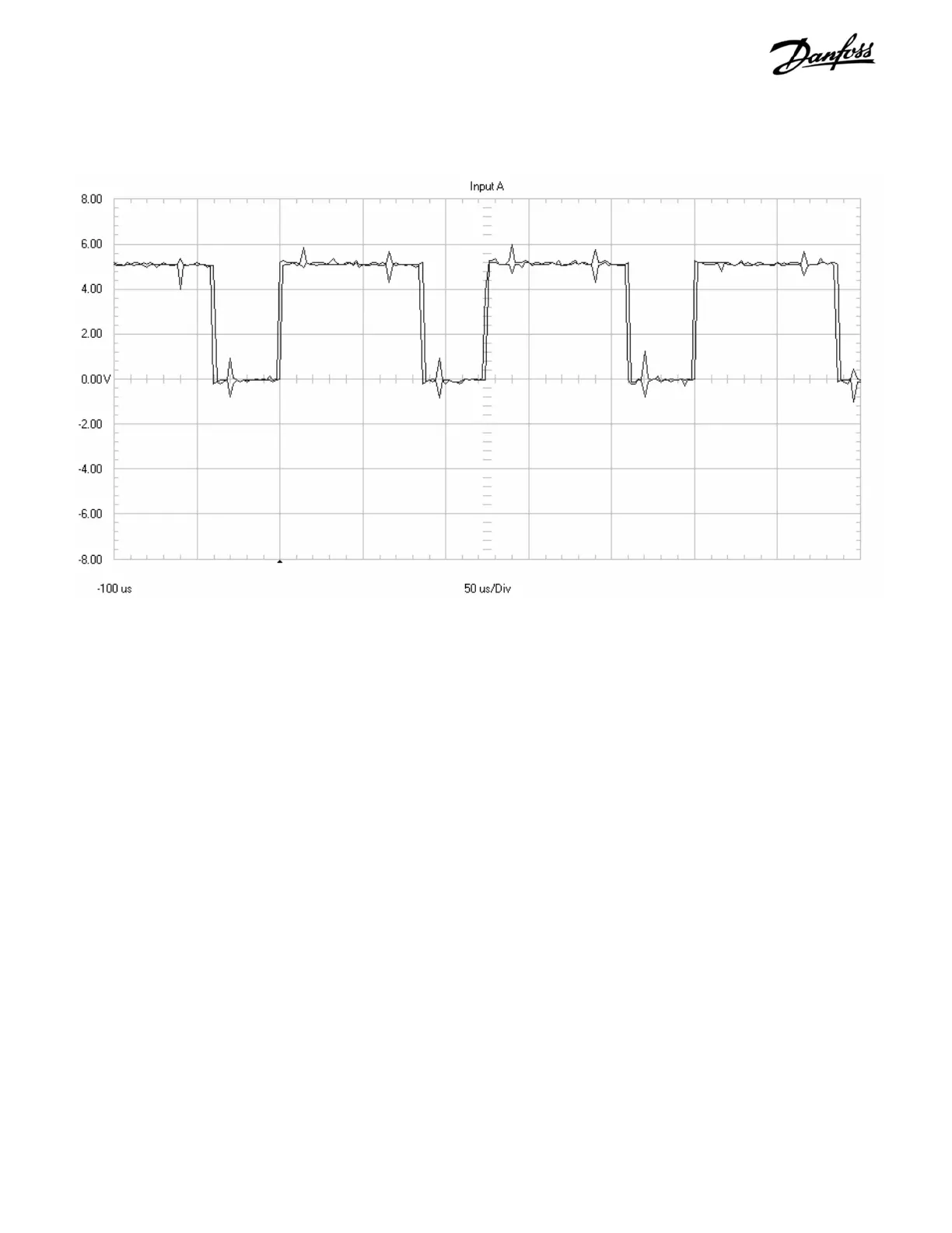
14. Place drive in run at 30 Hz.
The waveform should appear as in Figure 5-15.
15. Using a DVM, again check these same signal
board terminals. DVM should read 2.2 to 2.5
VDC.
An incorrect reading of a gate signal indicates either the power
card is defective or the signal has been lost prior to arriving at
the power card. There is no test to verify the signals directly
out of the control card. The power card would be suspected if
a single gate signal is incorrect. The control card would be
suspect if all six signals are incorrect. Replace the corresponding
card in accordance with the disassembly procedures in Section
6 or 7.
Figure 5-15. Gate Signal Waveform from Signal Test Board
IGBT Gate Signal measured with the Signal Test Board: 2 volts per division vertical scale, 50 microseconds per
division time scale. Unit running at 30 Hertz

Table of Contents

Other manuals for Danfoss VLT series

Questions and Answers:

Question and Answer IconNeed help?

Do you have a question about the Danfoss VLT series and is the answer not in the manual?

Danfoss VLT series Specifications

General IconGeneral
SeriesVLT
CategoryDC Drives
Output Voltage0-100% of input voltage
Protection FeaturesOvervoltage, Undervoltage, Overcurrent, Overtemperature, Short Circuit, Ground Fault
Communication InterfacesProfibus, CANopen
Enclosure RatingIP20, IP21, IP55, IP66
Cooling MethodForced Air Cooling, Convection Cooling
Control ModeSensorless Vector, Closed Loop Vector
Ambient Temperature-10°C to +50°C (14°F to 122°F)

Related product manuals