3.4.6 Torque
When tightening all connection of mains, it is important to
tighten with the correct torque. Too low or too high torque
results in a poor connection of mains. To ensure correct
torque, use a torque wrench.
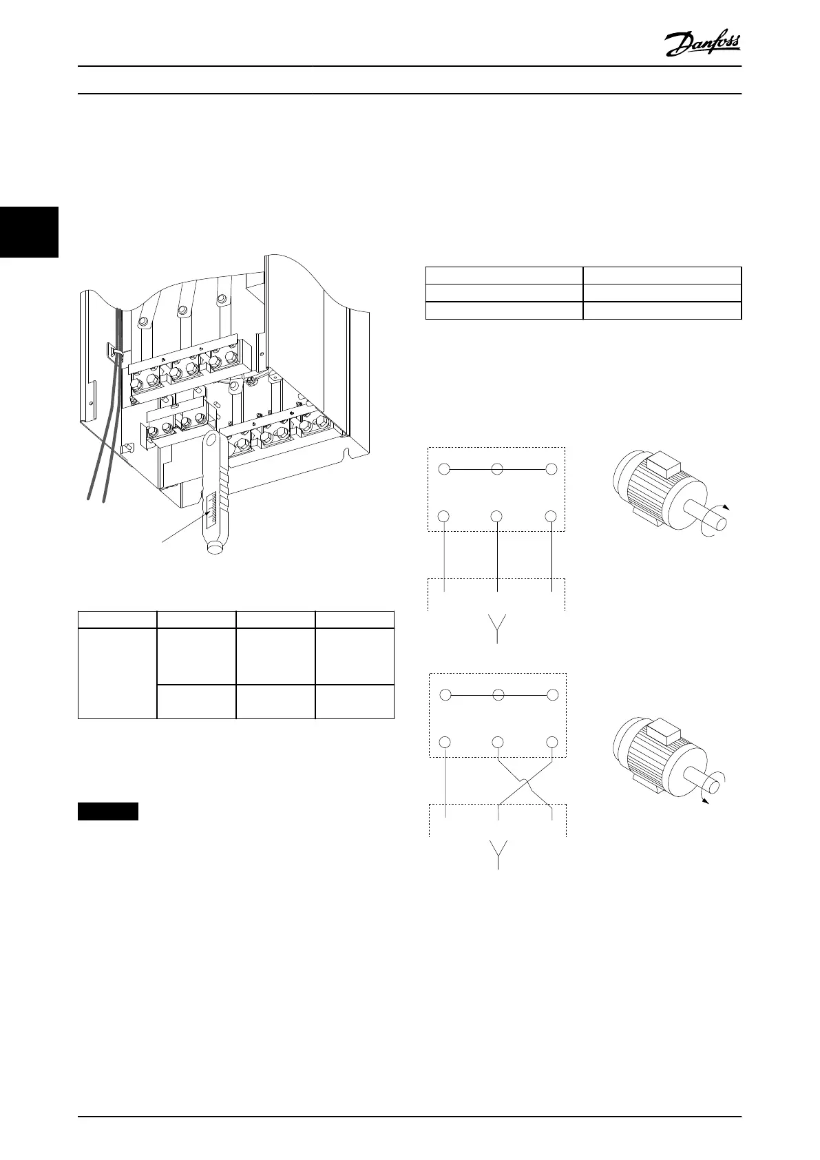
176FA247.12
Nm/in-lbs
-DC 88
+DC 89
R/L1 91
S/L2 92
T/L3 93
U/T1 96
V/T2 97
W/T3
Illustration 3.44 Tightening Torques
Enclosure size Terminal Torque Bolt size
F8–F15 Mains
Motor
19–40 Nm
(168–354 in-lb)
M10
Brake
Regen
8.5–20.5 Nm
(75–181 in-lb)
M8
Table 3.11 Tightening Torques
3.4.7 Shielded Cables
NOTICE
Danfoss recommends using shielded cables between the
LCL lter and the frequency converter. Unshielded cables
can be used between the transformer and the LCL lter
input side.
Make sure to connect shielded and armored cables
properly to ensure high EMC immunity and low emissions.
The connection can be made using either cable glands or
clamps.
•
EMC cable glands: Available cable glands can be
used to ensure optimum EMC connection.
•
EMC cable clamp: Clamps allowing easy
connection are supplied with the frequency
converter.
3.4.8 Motor Cable
Connect the motor to terminals U/T1/96, V/T2/97, W/T3/98.
Ground to terminal 99. All types of 3-phase asynchronous
standard motors can be used with a frequency converter.
The factory setting is for clockwise rotation with the
frequency converter output connected as follows:
Terminal number Function
96, 97, 98 Mains U/T1, V/T2, W/T3
99 Ground
Table 3.12 Motor Connection Terminals
•
Terminal U/T1/96 connected to U-phase.
•
Terminal V/T2/97 connected to V-phase.
•
Terminal W/T3/98 connected to W-phase.
175HA036.11
U
1
V
1
W
1
96 97 98
FC
Motor
U
2
V
2
W
2
U
1
V
1
W
1
96 97 98
FC
Motor
U
2
V
2
W
2
Illustration 3.45 Wiring for Clockwise and Counterclockwise
Motor Rotation
The direction of rotation can be changed by switching 2
phases in the motor cable or by changing the setting of
parameter 4-10 Motor Speed Direction.
A motor rotation check can be performed using
parameter 1-28 Motor Rotation Check and following the
steps shown on the display.
How to Install
VLT
®
AutomationDrive FC 302
46 Danfoss A/S © 04/2016 All rights reserved. MG34Q402
33