3.2 Mechanical Installation
3.2.1 Preparation for Installation
To ensure reliable and eective installation of the
frequency converter, make the following preparations:
•
Provide a suitable mounting arrangement. The
mounting arrangement depends on the design,
weight, and torque of the frequency converter.
•
To ensure that the space requirements are met,
examine the mechanical drawings.
•
Ensure that all wiring is done in accordance with
national regulations.
3.2.2 Tools Required
•
Drill with 10 mm or 12 mm bit.
•
Tape measure.
•
Wrench with relevant metric sockets (7–17 mm).
•
Extensions to wrench.
•
Sheet metal punch for conduits or cable glands in
IP21/NEMA 1 and IP54 units
•
Lifting bar to lift the unit (rod or tube maximum
Ø 25 mm (1 in), able to lift minimum 400 kg (880
lb).
•
Crane or other lifting aid to place the frequency
converter in position.
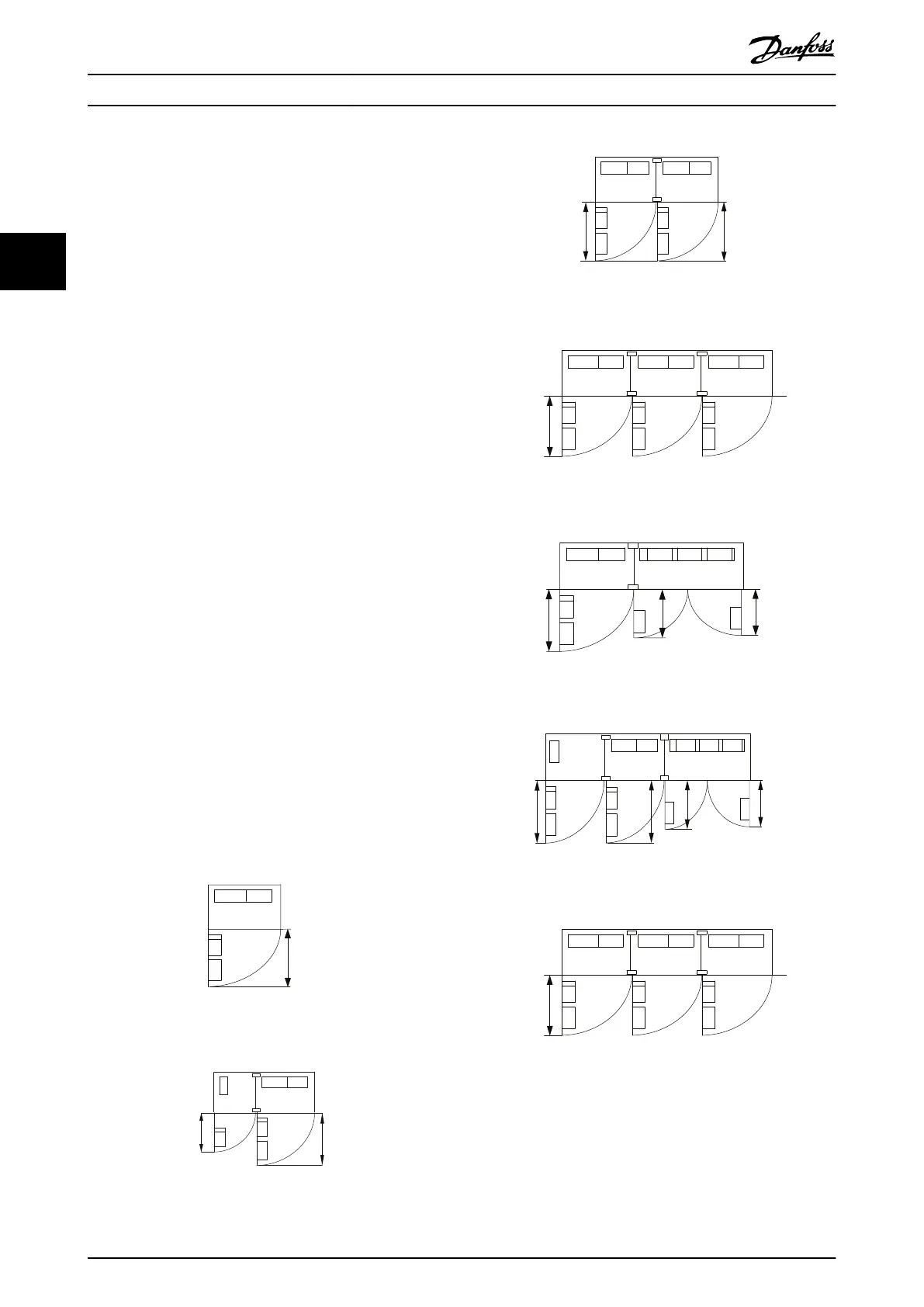
3.2.3 General Considerations
Space
To allow airow and cable access, ensure sucient space
above and below the frequency converter. In addition,
allow for enough space in front of the unit to open the
panel door, see Illustration 3.5 to Illustration 3.12.
Illustration 3.5 Space in Front of Enclosure Size F8
130BB003.13
776
(30.6)
578
(22.8)
Illustration 3.6 Space in Front of Enclosure Size F9
776
(30.6)
776
(30.6)
130BB574.10
Illustration 3.7 Space in Front of Enclosure Size F10
130BB575.10
776 (30.6)
(2x)
Illustration 3.8 Space in Front of Enclosure Size F11
130BB576.10
776
(30.6)
624
(24.6)
579
(22.8)
Illustration 3.9 Space in Front of Enclosure Size F12
130BB577.10
776
(30.6)
776
(30.6)
624
(24.6)
579
(22.8)
Illustration 3.10 Space in Front of Enclosure Size F13
130BB575.10
776 (30.6)
(2x)
Illustration 3.11 Space in Front of Enclosure Size F14
How to Install
VLT
®
AutomationDrive FC 302
18 Danfoss A/S © 04/2016 All rights reserved. MG34Q402
33