3.7.2 Parallel Connection of Motors
The frequency converter can control several parallel-
connected motors. The total current consumption of the
motors must not exceed the rated output current I
M,N
for
the frequency converter.
NOTICE
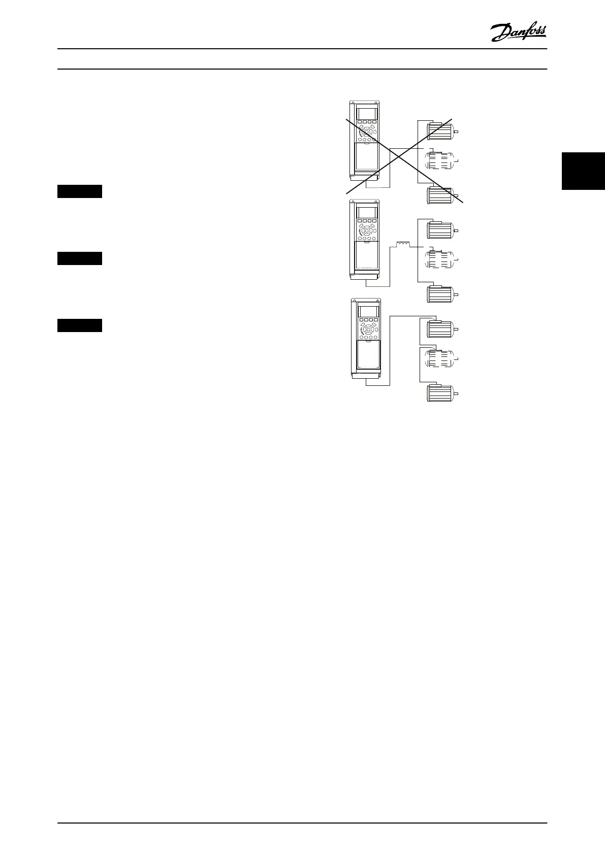
Installations with cables connected in a common joint as
in Illustration 3.61 are only recommended for short cable
lengths.
NOTICE
When motors are connected in parallel,
parameter 1-29 Automatic Motor Adaptation (AMA) cannot
be used.
NOTICE
The electronic thermal relay (ETR) of the frequency
converter cannot be used as motor overload protection
for the individual motor in systems with parallel-
connected motors. Provide further motor overload
protection, for example thermistors in each motor or
individual thermal relays (circuit breakers are not
suitable as protection).
Problems can occur at start-up and at low RPM values if
motor sizes are widely dierent because relatively high
ohmic resistance in the stator of small motors calls for a
higher voltage at start-up and at low RPM values.
Illustration 3.61 Parallel Motor Connection
3.7.3 Motor Thermal Protection
The electronic thermal relay (ETR) provides the overload
protection. When the current is high, the ETR activates the
trip function. The trip response time varies with the current
magnitude inversely. The overload trip function provides
the Class 20 motor overload protection.
The electronic thermal relay in the frequency converter has
received UL Approval for single motor overload protection,
when parameter 1-90 Motor Thermal Protection is set to [4]
ETR Trip and parameter 1-24 Motor Current is set to the
rated motor current (see motor nameplate).
For motor thermal protection, it is also possible to use the
VLT
®
PTC Thermistor Card MCB 112 option. This card
provides ATEX certicate to protect motors in explosion
hazardous areas, Zone 1/21, and Zone 2/22. When
parameter 1-90 Motor Thermal Protection is set to [20] ATEX
ETR and is combined with the use of MCB 112, it is
possible to control an Ex-e motor in explosion hazardous
areas. Consult the relevant programming guide for details
on how to set up the frequency converter for safe
operation of Ex-e motors.
How to Install Operating Instructions
MG34Q402 Danfoss A/S © 04/2016 All rights reserved. 59
3 3