Wire type and ratings
•
All wiring must comply with local and national
regulations regarding cross-section and ambient
temperature requirements.
•
Power connection wire recommendation:
Minimum 75 °C (167 °F) rated copper wire.
See chapter 5.6 Electrical Data for recommended wire sizes
and types.
CAUTION
PROPERTY DAMAGE!
Protection against motor overload is not included in the
default setting. To add this function, set
parameter 1-90 Motor Thermal Protection to [ETR trip] or
[ETR warning]. For the North American market, the ETR
function provides class 20 motor overload protection in
accordance with NEC. Failure to set parameter 1-90 Motor
Thermal Protection to [ETR trip] or [ETR warning] means
that motor overload protection is not provided and
property damage can occur if the motor overheats.
3.4.1 Transformer Selection
Use the frequency converter with a 12-pulse isolation
transformer.
3.4.2 Power Connections
Cabling and fusing
NOTICE
All cabling must comply with national and local
regulations on cable cross-sections and ambient
temperature. UL applications require 75 °C copper
conductors. 75 °C (167 °F) and 90 °C (194 °F) copper
conductors are thermally acceptable for the frequency
converter to use in non-UL applications.
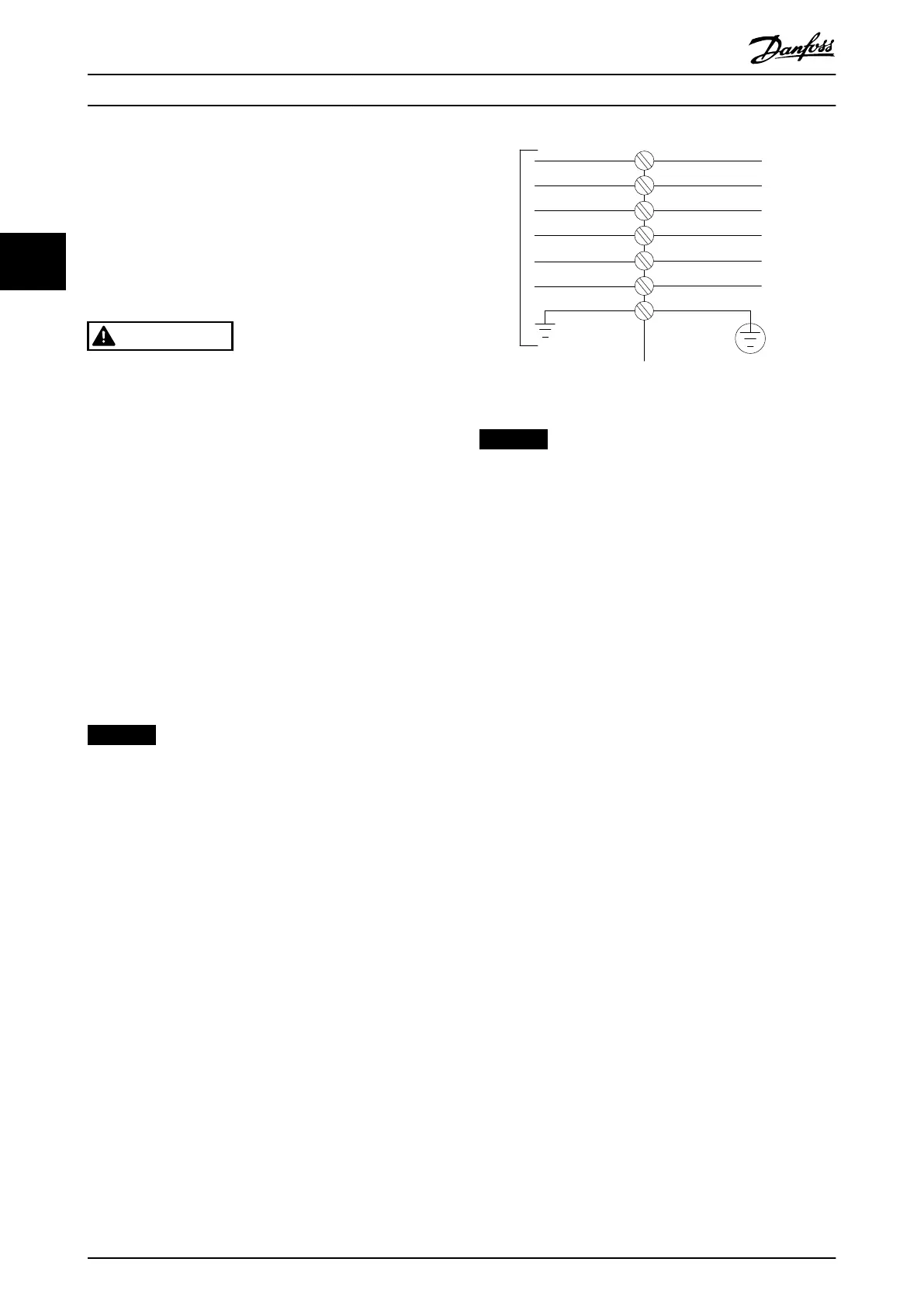
The power cable connections are located as in
Illustration 3.32. Dimensioning of the cable cross-section
must be done in accordance with the current ratings and
local legislation. See chapter 5.1 Mains Supply for details.
For protection of the frequency converter, use the
recommended fuses, or ensure that the unit has built-in
fuses. Recommended fuses are detailed in in
chapter 3.4.13 Fuses. Always ensure that fusing conforms to
local regulations.
If the mains switch is included, the connection of mains is
tted to the mains switch.
6 Phase
power
input
130BB693.10
91-1 (L1-1)
92-1 (L2-1)
93-1 (L3-1)
91-2
92-2
93-2
95 PE
(L2-2)
(L1-2)
(L3-2)
Illustration 3.32 Power Cable Connections
NOTICE
If an unshielded/unarmored cable is used, some EMC
requirements are not complied with. To comply with EMC
emission specications, use a shielded/armored motor
cable. For more information, see EMC Specications in the
product relevant design guide.
How to Install
VLT
®
AutomationDrive FC 302
36 Danfoss A/S © 04/2016 All rights reserved. MG34Q402
33