EasyManuals Logo

Danfoss VLT series User Manual

Danfoss VLT series
98 pages
To Next Page IconTo Next Page
To Previous Page IconTo Previous Page
Page #39 background imageLoading...
Page #39 background image
See chapter 5.1 Mains Supply for the correct dimensioning of the motor cable cross-section and length.
NOTICE
Only use the cross-section the eld wiring terminals are
designed for. The terminals do not accept a wire of 1 size
large.
91-1
92-1
93-1
91-2
92-2
93-2
S1
T1
R1
S2
T2
R2
95
Rectier 1
Rectier 2
Inverter1
F8/F9
Inverter2
F10/F11
Inverter3
F12/F13
130BC036.11
91-1
92-1
93-1
91-2
92-2
93-2
S1
T1
R1
S2
T2
R2
95
Rectier 1
Rectier 2
Inverter1
F8/F9
Inverter2
F10/F11
Inverter3
F12/F13
A
B
Inverter4
F14/F15
Inverter4
F14/F15
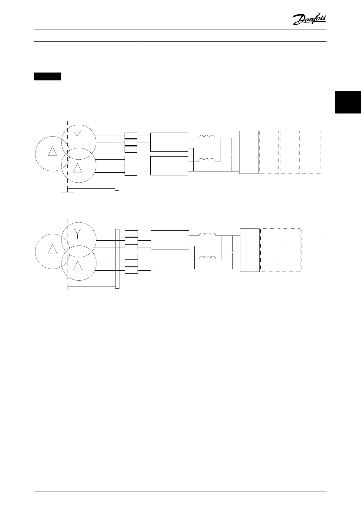
Illustration 3.33 A) Temporary 6-Pulse Connection
1)
B) 12-Pulse Connection
Notes
1) When 1 of the rectier modules is inoperable, use the operable rectier module to run the frequency converter at a
reduced power. Contact Danfoss for reconnection details.
How to Install Operating Instructions
MG34Q402 Danfoss A/S © 04/2016 All rights reserved. 37
3 3

Table of Contents

Other manuals for Danfoss VLT series

Questions and Answers:

Question and Answer IconNeed help?

Do you have a question about the Danfoss VLT series and is the answer not in the manual?

Danfoss VLT series Specifications

General IconGeneral
SeriesVLT
CategoryDC Drives
Output Voltage0-100% of input voltage
Protection FeaturesOvervoltage, Undervoltage, Overcurrent, Overtemperature, Short Circuit, Ground Fault
Communication InterfacesProfibus, CANopen
Enclosure RatingIP20, IP21, IP55, IP66
Cooling MethodForced Air Cooling, Convection Cooling
Control ModeSensorless Vector, Closed Loop Vector
Ambient Temperature-10°C to +50°C (14°F to 122°F)

Related product manuals