3.4.18 Control Cable Routing
Tie all control wires down to the designated control cable
routing. Remember to connect the shields in a proper way
to ensure optimum electrical immunity.
Fieldbus connection
Connections are made to the relevant options on the
control card. For details, see the relevant eldbus
instruction. Place the cable in the provided path inside the
frequency converter and tie it down with other control
wires.
Installation of 24 V DC external supply
•
Torque: 0.5–0.6 Nm (5 in-lb)
•
Screw size: M3
Terminal
number
Function
35 (-), 36 (+) 24 V DC external supply
Table 3.30 Terminals for 24 V DC external supply
24 V DC external supply can be used as low voltage supply
to the control card and any option cards installed. This
enables full operation of the LCP (including parameter
setting) without connection to the mains. A warning of low
voltage is given when 24 V DC has been connected;
however, there is no tripping.
NOTICE
To ensure correct galvanic isolation (type PELV) on the
control terminals of the frequency converter, use 24 V
DC PELV supply.
3.4.19 Access to Control Terminals
All terminals to the control cables are located beneath the
LCP. They are accessed by opening the door of the IP21/
IP54 unit, or by removing the covers of the IP00 unit.
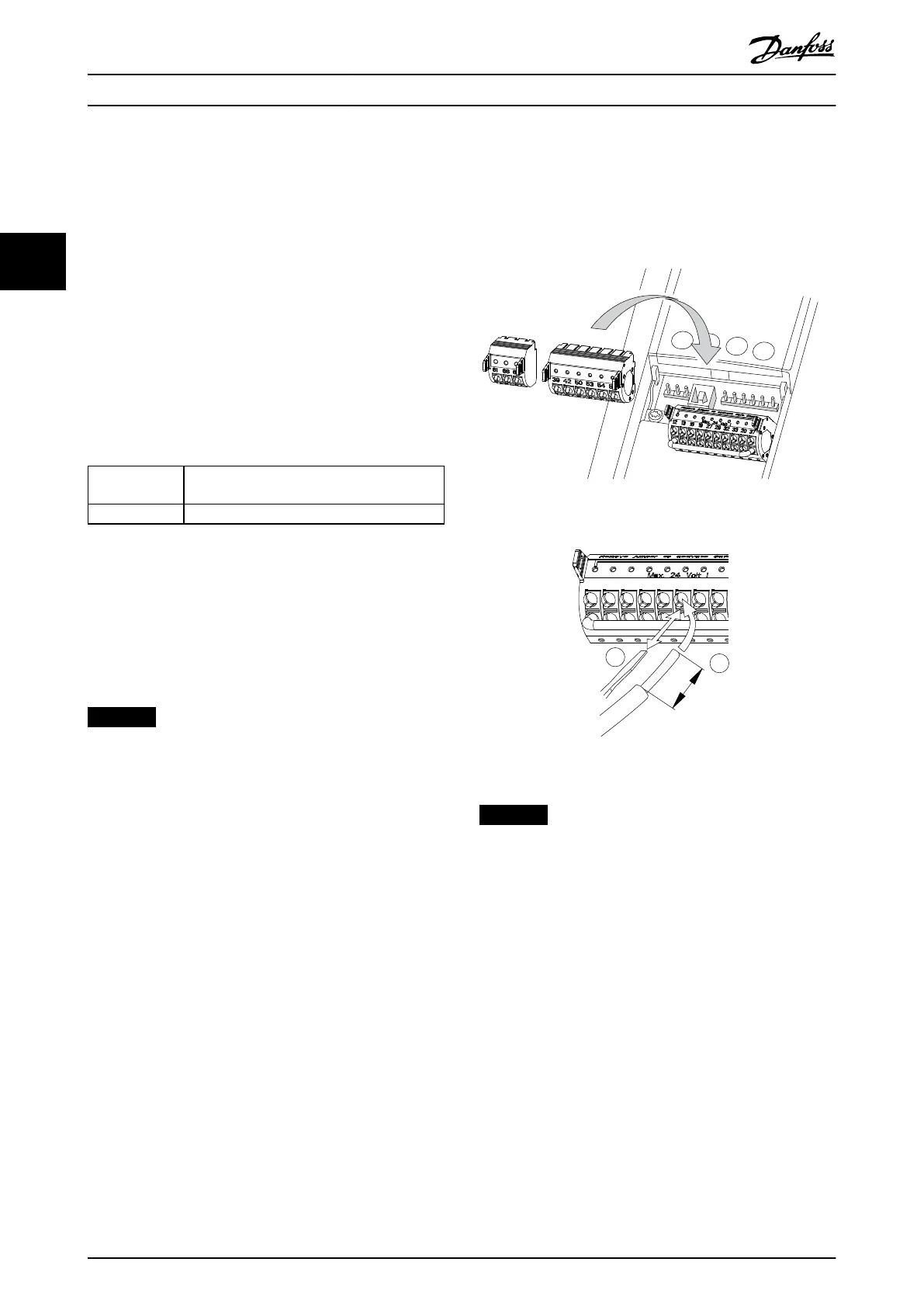
3.4.20 Wiring to Control Terminals
Control terminal connectors can be unplugged from the
frequency converter for ease of installation, as shown in
Illustration 3.48.
Illustration 3.48 Unplugging Control Terminals
130BD546.11
2
1
10 mm
[0.4 inches]
12 13 18 19 27 29 32 33
Illustration 3.49 Connecting Control Wires
NOTICE
To minimize interference, keep control wires as short as
possible and separate from high-power cables.
1. Open the contact by inserting a small screwdriver
into the slot above the contact and push the
screwdriver slightly upwards.
2. Insert the bare control wire into the contact.
3. To fasten the control wire into the contact,
remove the screwdriver.
4. Ensure that the contact is rmly established and
not loose. Loose control wiring can be the source
of equipment faults or reduced performance.
See chapter 5.4 Cable Specications for control terminal
wiring sizes and chapter 3.5 Connection Examples for typical
control wiring connections.
How to Install
VLT
®
AutomationDrive FC 302
52 Danfoss A/S © 04/2016 All rights reserved. MG34Q402
33