3.5.3 Speed up/Speed down
Terminals 29/32 = Speed up/Speed down
Terminal 18 = Parameter 5-10 Terminal 18 Digital
Input [9] Start (default).
Terminal 27 = Parameter 5-12 Terminal 27 Digital
Input [19] Freeze reference.
Terminal 29 = Parameter 5-13 Terminal 29 Digital
Input [21] Speed up.
Terminal 32 = Parameter 5-14 Terminal 32 Digital
Input [22] Speed down.
NOTICE
Terminal 29 only in FC x02 (x=series type).
12
18
27
29
32
37
+24V
Par. 5-10
Par. 5-12
Par. 5-13
Par. 5-14
130BA021.12
Illustration 3.58 Speed up/Speed down
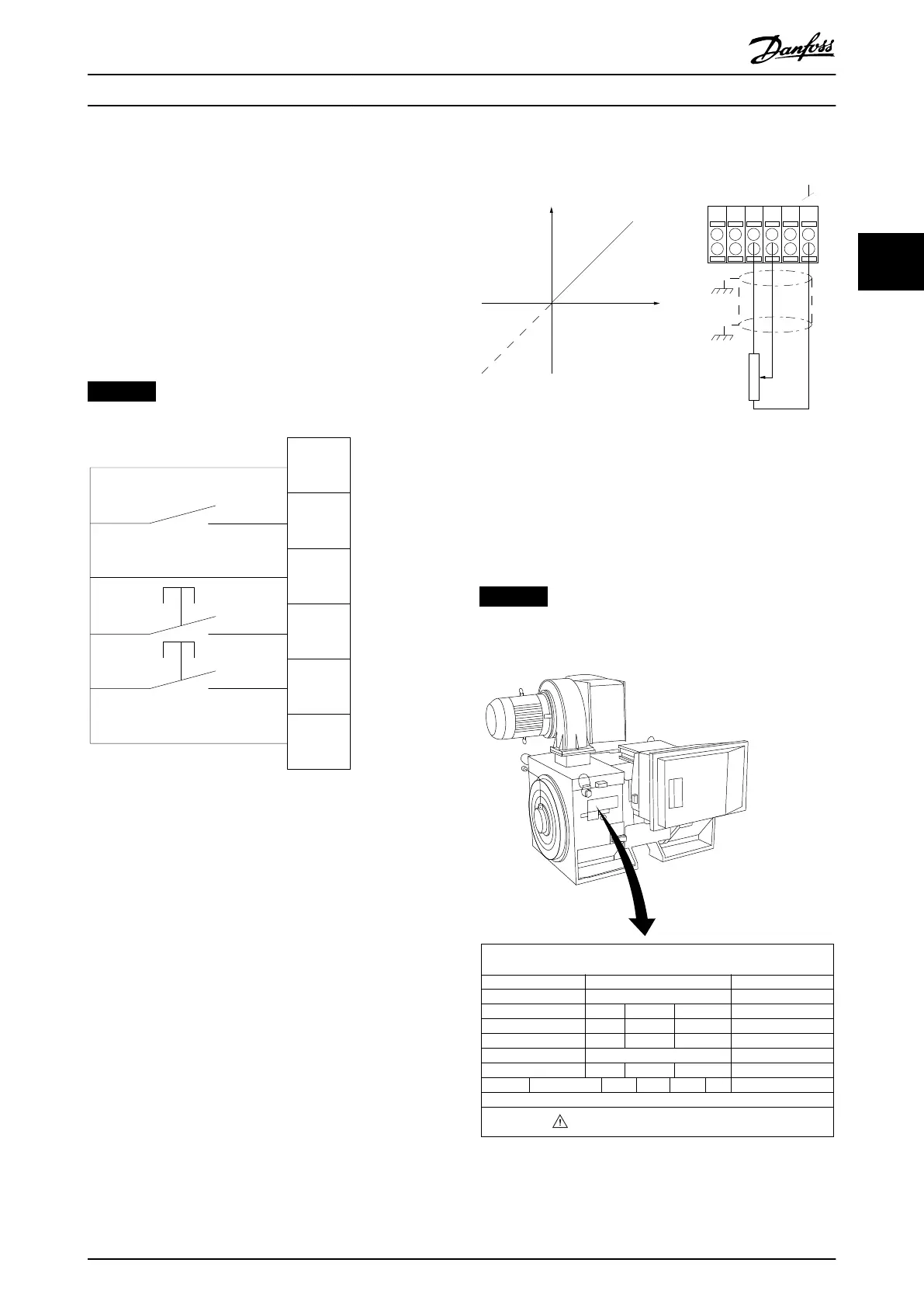
3.5.4 Potentiometer Reference
Voltage reference via a potentiometer
Reference source 1 = [1] Analog input 53 (default).
Terminal 53, low voltage = 0 V.
Terminal 53, high voltage = 10 V.
Terminal 53, low reference/feedback = 0 RPM.
Terminal 53, high reference/feedback = 1500 RPM.
Switch S201 = OFF (U)
130BA154.11
555039 42 53 54
Speed RPM
P 6-15
1 kΩ
+10V/30mA
Ref. voltage
P 6-11 10V
Illustration 3.59 Potentiometer Reference
3.6 Final Set-up and Test
To test the set-up and to ensure that the frequency
converter is running, follow these steps.
Step 1. Locate the motor nameplate.
NOTICE
The motor is either star (Y) or delta connected (Δ). This
information is on the motor nameplate.
THREE PHASE INDUCTION MOTOR
kW
400
MOD
MCV 315E
Nr.
135189 12 04
PRIMARY
SECONDARY
V
690
A
V A
V A
V A
410.6 CONN Y
CONN
CONN
CONN ENCLOSURE
CAUTION
COS f
ALT
RISE
m
SF
1.15
0.85
AMB
40
1000
80
°C
°C
IP23
40
IL/IN
6.5
HP
536
mm
1481
Hz
DESIGN
50
N
DUTY
INSUL WEIGHT 1.83 ton
EFFICIENCY %
95.8% 95.8% 75%100%
S1
I
130BA767.10
Illustration 3.60 Nameplate
How to Install Operating Instructions
MG34Q402 Danfoss A/S © 04/2016 All rights reserved. 57
3 3