Requirements
F8/F9 requirements: The cables must be of equal length
within 10% between the inverter module terminals and the
rst common point of a phase. The recommended
common point is the motor terminals.
F10/F11 requirements: Motor phase cable quantities must
be multiples of 2, resulting in 2, 4, 6, or 8 (1 cable is not
allowed) to obtain equal number of wires attached to both
inverter module terminals. The cables must be equal
length within 10% between the inverter module terminals
and the rst common point of a phase. The recommended
common point is the motor terminals.
F12/F13 requirements: Motor phase cable quantities must
be multiples of 3, resulting in 3, 6, 9, or 12 (1, 2, or 3
cables are not allowed) to obtain an equal number of wires
attached to each inverter module terminal. The wires must
be of equal length within 10% between the inverter
module terminals and the rst common point of a phase.
The recommended common point is the motor terminals.
F14/F15 requirements: Motor phase cable quantities must
be multiples of 4, resulting in 4, 8, 12, or 16 (1, 2, or 3
cables are not allowed) to obtain an equal number of wires
attached to each inverter module terminal. The wires must
be of equal length within 10% between the inverter
module terminals and the rst common point of a phase.
The recommended common point is the motor terminals.
Output junction box requirements: The length, minimum
2.500 mm (98.4 in), and quantity of cables must be equal
from each inverter module to the common terminal in the
junction box.
NOTICE
If a retrot application requires an unequal number of
wires per phase, consult Danfoss for requirements and
documentation, or use the top/bottom entry side cabinet
option.
3.4.9 Brake Cable for Frequency Converters
with Factory-installed Brake Chopper
Option
(Only standard with letter B in position 18 of product type
code).
Use a shielded connection cable to the brake resistor. The
maximum length from the frequency converter to the DC
bar is limited to 25 m (82 ft).
Terminal number Function
81, 82 Brake resistor terminals
Table 3.13 Brake Resistor Terminals
The connection cable to the brake resistor must be
shielded. Connect the shield to the conductive backplate
on the frequency converter and to the metal cabinet of
the brake resistor with cable clamps.
Size the brake cable cross-section to match the brake
torque. See also the instructions Brake Resistor and Brake
Resistors for Horizontal Applications for further information
regarding safe installation.
NOTICE
Depending on the supply voltage, voltages up to 1099 V
DC can occur on the terminals.
F enclosure requirements
Connect the brake resistor to the brake terminals in each
inverter module.
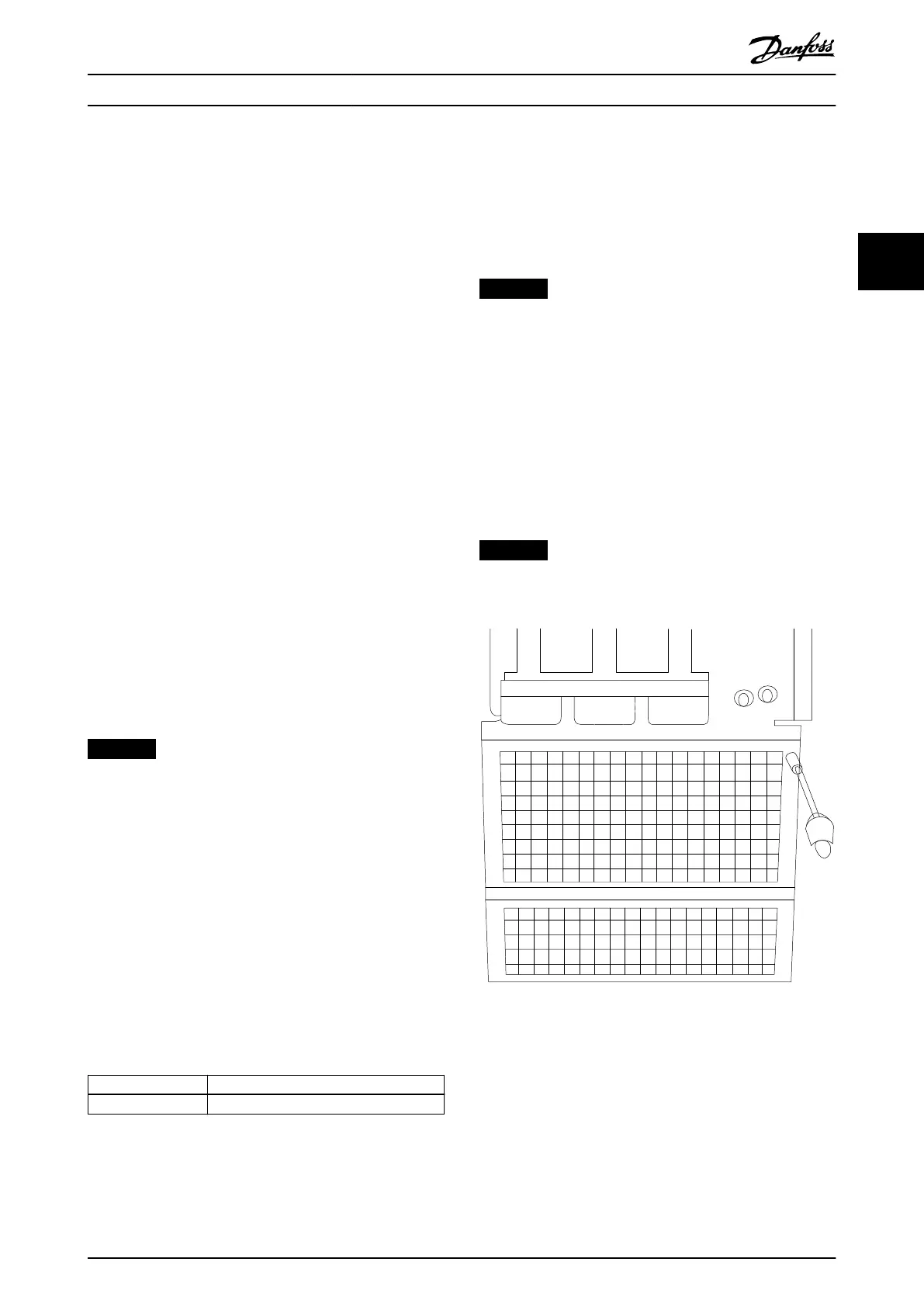
3.4.10 Shielding against Electrical Noise
Before mounting the mains power cable, mount the EMC
metal cover to ensure best EMC performance.
NOTICE
The EMC metal cover is only included in frequency
converters with an RFI lter.
Illustration 3.46 Mounting of EMC shield
How to Install Operating Instructions
MG34Q402 Danfoss A/S © 04/2016 All rights reserved. 47
3 3