3.2.4 Terminal Locations, F8–F15
The F enclosures are available in 8 dierent sizes. The F8 consists of the rectier and inverter modules in 1 cabinet. The F10,
F12, and F14 consist of a rectier cabinet on the left and an inverter cabinet on the right. The F9, F11, F13, and F15 have
the option cabinet added to the F8, F10, F12, and F14, respectively.
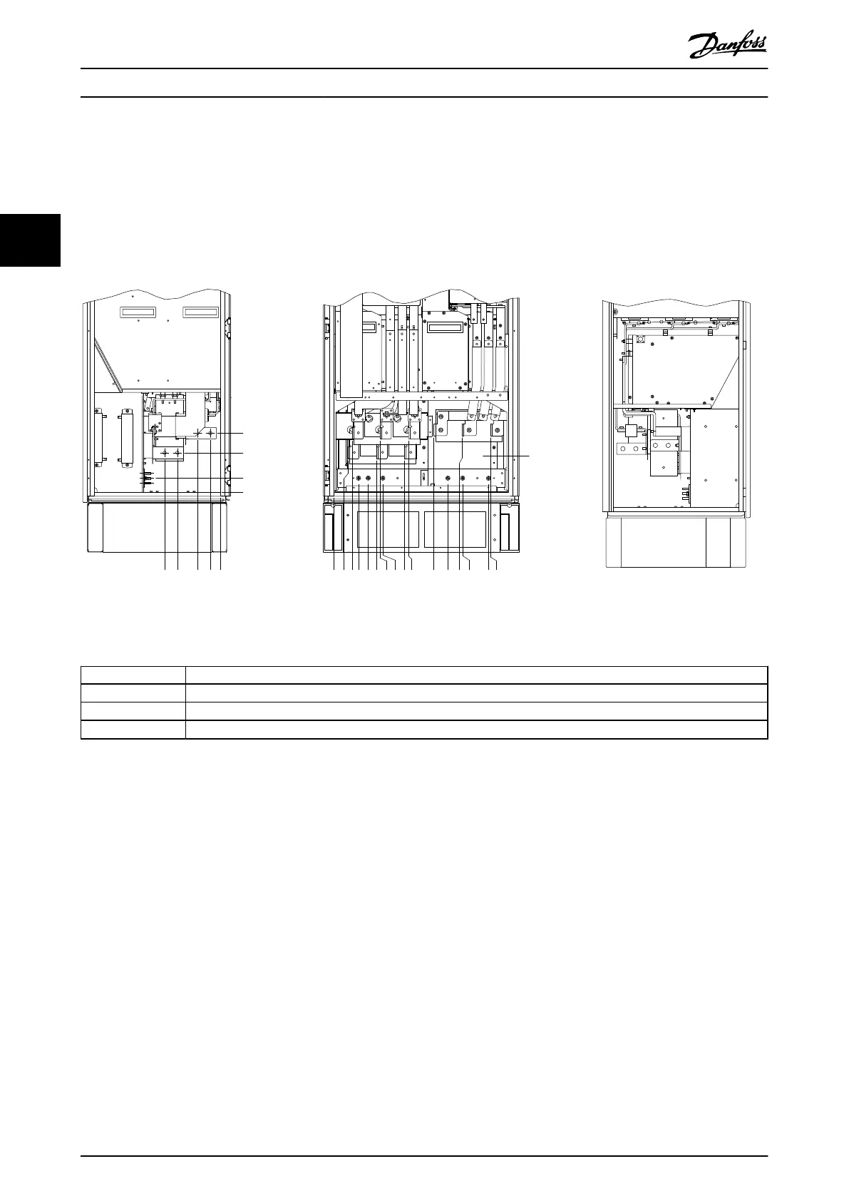
3.2.4.1 Inverter and Rectier, Enclosure Sizes F8, and F9
4
3
239.6 [ 9.43 ]
0.0 [ 0.00 ]
0.0 [ 0.00 ]
160.0 [ 6.30 ]
56.6 [ 2.23 ]
39.8 [ 1.57 ]
91.8 [ 3.61 ]
174.1 [ 6.85 ]
226.1 [ 8.90 ]
130BB534.11
R2/L12
R1/L11
91-1
91
S2/L22
S1/L21
92-1
T2/L32 93-1
92
T1/L31 93
U/T1 96 V/T2 97 W/T3 98
0.0 [ 0.00 ]
57.6 [ 2.27 ]
74.0 [ 2.91 ]
100.4 [ 3.95 ]
139.4 [ 5.49 ]
172.6 [ 6.80 ]
189.0 [ 7.44 ]
199.4 [ 7.85 ]
287.6 [ 11.32 ]
304.0 [ 11.97 ]
407.3 [ 16.04 ]
464.4 [ 18.28 ]
522.3 [ 20.56 ]
524.4 [ 20.65 ]
629.7 [ 24.79 ]
637.3 [ 25.09 ]
1 2
1 Left side view
2 Front view
3 Right side view
4 Ground bar
Illustration 3.13 Terminal Locations Inverter and Rectier, Enclosure Sizes F8, and F9. The gland plate is 42 mm (1.65 in) below 0.0
level.
How to Install
VLT
®
AutomationDrive FC 302
20 Danfoss A/S © 04/2016 All rights reserved. MG34Q402
33