Shielding of cables
Avoid installation with twisted shield ends (pigtails). They
spoil the shielding eect at higher frequencies. If it is
necessary to break the shield to install a motor isolator or
motor contactor, the shield must be continued at the
lowest possible HF impedance.
Connect the motor cable shield to both the decoupling
plate of the frequency converter and to the metal housing
of the motor.
Make the shield connections with the largest possible
surface area (cable clamp). For this purpose, use the
supplied installation devices within the frequency
converter.
Cable length and cross-section
The frequency converter has been EMC tested with a given
cable length. Keep the motor cable as short as possible to
reduce the noise level and leakage currents.
Switching frequency
When frequency converters are used with sine-wave lters
to reduce the acoustic noise from a motor, set the
switching frequency according to the instruction in
parameter 14-01 Switching Frequency.
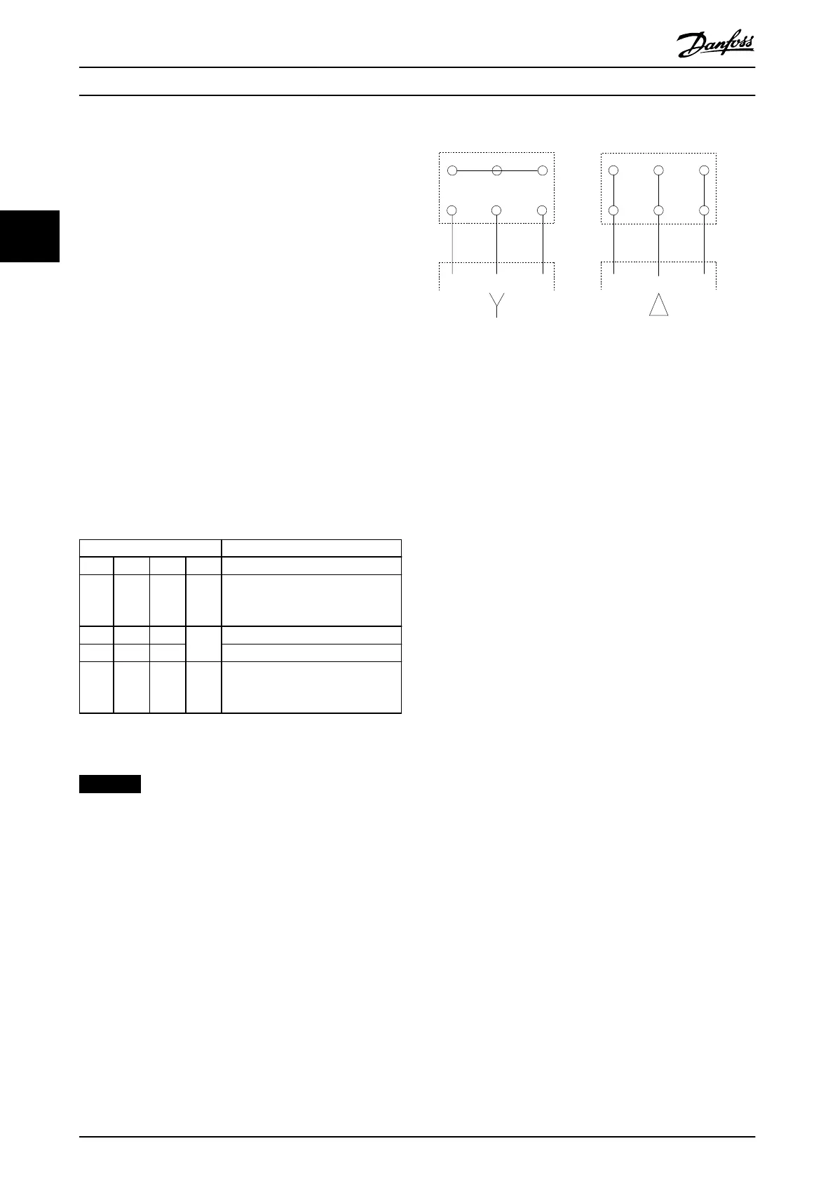
Term. no.
96 97 98 99
U V W
PE
1)
Motor voltage 0–100% of mains
voltage.
3 wires out of motor
U1 V1 W1
PE
1)
Delta-connected
W2 U2 V2 6 wires out of motor
U1 V1 W1
PE
1)
Star-connected U2, V2, W2
U2, V2, and W2 to be intercon-
nected separately.
Table 3.10 Terminal Connections
1) Protective Earth connection
NOTICE
In motors without phase insulation paper or other
insulation reinforcement suitable for operation with
voltage supply (such as a frequency converter), t a sine-
wave lter on the output of the frequency converter.
U
1
V
1
W
1
175ZA114.11
96 97 98
96 97 98
FC
FC
Motor
Motor
U
2
V
2
W
2
U
1
V
1
W
1
U
2
V
2
W
2
Illustration 3.34 Star and Delta Connections
How to Install
VLT
®
AutomationDrive FC 302
38 Danfoss A/S © 04/2016 All rights reserved. MG34Q402
33