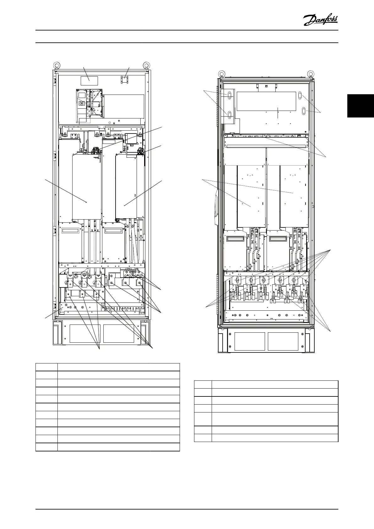
1 Brake resistor temperature switch
2 Auxiliary relay (01, 02, 03, 04, 05, 06)
3 SCR enable/disable
4 Auxiliary fan (100, 101, 102, 103)
5 Inverter module
6 Brake terminals 81 (-R), 82 (+R)
7 Motor connection T1 (U), T2 (V), T3 (W)
8 Mains L2-1 (R2), L2-2 (S2), L3-2 (T2)
9 Mains L1-1 (R1), L2-1 (S1), L3-1 (T1)
10 Ground PE terminals
11 12-pulse rectier module
Illustration 3.35 Rectier and Inverter Cabinet, Enclosure Sizes
F8 and F9
1 DC-bus connections for common DC-bus (DC+, DC-)
2 DC-bus connections for common DC-bus (DC+, DC-)
3 AUX fan (100, 101, 102, 103)
4 Mains fuses F10/F12 (6 pieces)
5 Mains L1-2 (R2), L2-2 (S2), L3-2 (T2)
6 Mains L1-1 (R1), L2-1 (S1), L3-1 (T1)
7 12-pulse rectier module
Illustration 3.36 Rectier Cabinet, Enclosure Sizes F10 and F12
How to Install Operating Instructions
MG34Q402 Danfoss A/S © 04/2016 All rights reserved. 39
3 3