Page 18 of 56
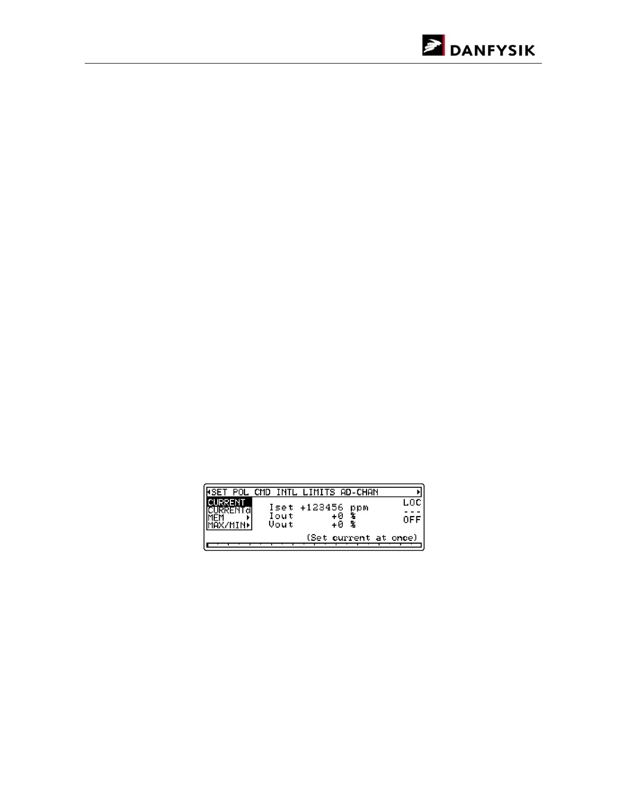
Bar Graph:
The bar graph is an analogue representation of the actual output current. The output current is
100% when the bar graph is full. The slim vertical lines marks are for 5% steps and the thick
vertical lines marks 10% steps. Therefore, each pixel represents 0.5%.
Status area:
The status area provides a quick overview of the present control status of the power supply
These include:
Control mode. LOCal or REMote. Remote is displayed inversed.
Regulation status. ReaDY or not Ready. “Ready” is highlighted in reverse video and “Not
ready” as three bars.
Main power. ON or OFF. OFF is highlighted in reverse video.
The address in a multi-drop configuration. Blank if not enabled.
Information area:
The bottom right corner of the display is reserved for various information purposes. These are:
The time taken from the SMD control module is shown if nothing else is to be displayed.
INTERLOCK — present if an interlock is pending (in default window).
STATUS — present if a particular status is pending, normally a transistor fault.
Help text in menus.
Menu Window:
Press the MENU key to display the Menu window. The screenshot below shows the initial
window when no interlocks are present and after the “” key is pressed once.