Page 24 of 56
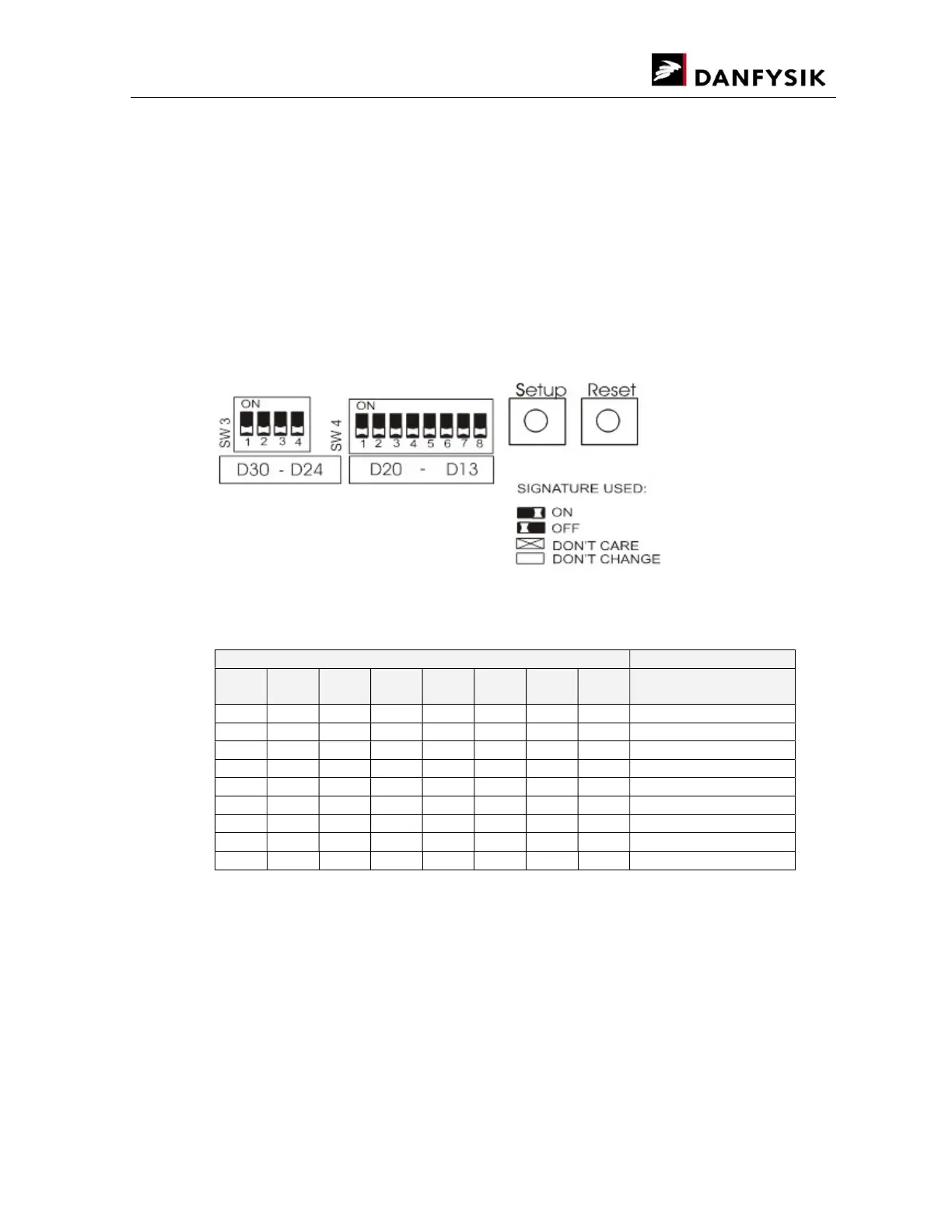
If one of the setup modes is selected, the yellow LED D24 below switch SW3 will illuminate and
indicate that the setup port is activated. The eight red LEDs, D13-D20 below switch SW4 will
show the present parameter of selected mode. Changing SW4 has no immediate effect, only
after pressing S4 SETUP, will the red LEDs (D13 to D20) take the same indication as SW4.
Be careful when changing the baud rates, an incorrect setting may cause communication loss.
Modifying a baud rate with the HW switches or by the appropriate SW command, will first take
effect after a reset. At the remote line, use command ESC<CPURESET to make a reset.
For switch settings, the following terminology is used:
Interlock LED indications (Mode 0)
red LED
LED
13
LED
14
LED
15
LED
16
LED
17
LED
18
LED
19
LED
20
Status
OFF OFF OFF OFF OFF OFF OFF OFF NO interlocks
ON External interlock 0/1
ON External interlock 2/3
ON Fan
ON Earth Leakage
ON Overtemp
ON AC Line fault
ON Overcurrent
ON Overvoltage
If all interlocks occur, all 8 red LEDs will illuminate.
When the interlocks are removed, the interlock LED indications can be reset by pressing the
RESET button on the display board (the red LEDs turn off).