Page 42 of 56
3.3.5.3. Auto Slew Rate Ramp Profile method
With the “Auto Slew Rate Ramp Profile Method”, an automatic ramp profile is generated and
executed when issuing a new current set point. In other words, this feature acts like a
software-riven slew rate controller.
Two shapes can be preselected. A cosine and a square shape. The selection of shape is given
by the Aux2 setting bit 4. 0 = Cosines & 1 = Square
For example: If the power supply is at 10% output current, the slew rate is set to 1 second
(‘esc’<slope time 1.1) and a set command “da 0.600000" is given, the power supply will start at
10% and run to 60% within ½ a second with the selected shape.
The positive and negative slew rate values can be set individually. Please refer to the SW
manual describing the “‘esc’< slope time ‘val1',’val2'” for further information.
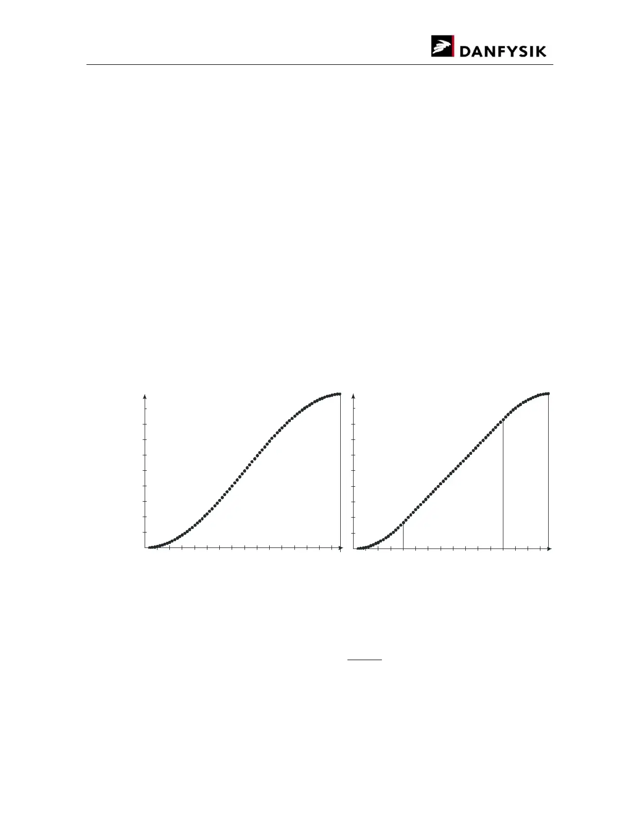
The two ramp profile shapes both have their benefits and disadvantages. The cosines shape is
smooth all the way, but has a higher di/dt in the middle and results in a sinus output voltage
shape on an inductive load, whereas the square shapes in a trapezoidal output voltage.
The ramp profile consists of 80 points with HW interpolated points in between. Each of the 80
points has a distance of 2.5 ms. In-between profiles with shorter distances than 200ms
(80*2.5ms) are achieved by omitting points. For example, a ramp time of 20ms will only consist
of 8 points thereby resulting in a coarser profile.
The figures below show the shape of the two ramp profiles.
Relative current
value
Cosines
start at -
π
Relative
Time from
Current set
3/4 1
Relative
Time from
Current set
Relative current
value
Square
Square
Linear
Cosines ramp shape Quadratic ramp shape
The time slot must be given as a multiple of 1.25ms. Between 1.25ms to 1 second. Any value
in-between will automatically be rounded off according to formulae:
= (
0.00125
) × 0.00125
The ramp profile can be stopped either with a “STOP” command or when the MPS is turned
OFF. The state of the ramp profile can be read through the “RR” command.