INSTALLATION
11
2
Pin RS232 RS485
Full-Duplex
RS485
Half-Duplex
20 mA C.L.
(INT-22 Only)
24,29 TX232 TX485+ RTX485+ CL OUT+
25,30 RTS232 TX485- RTX485- CL OUT-
26,31 SGND SGND SGND
32 RX232 RX485+ CL IN+
33 CTS232 RX485- CL IN-
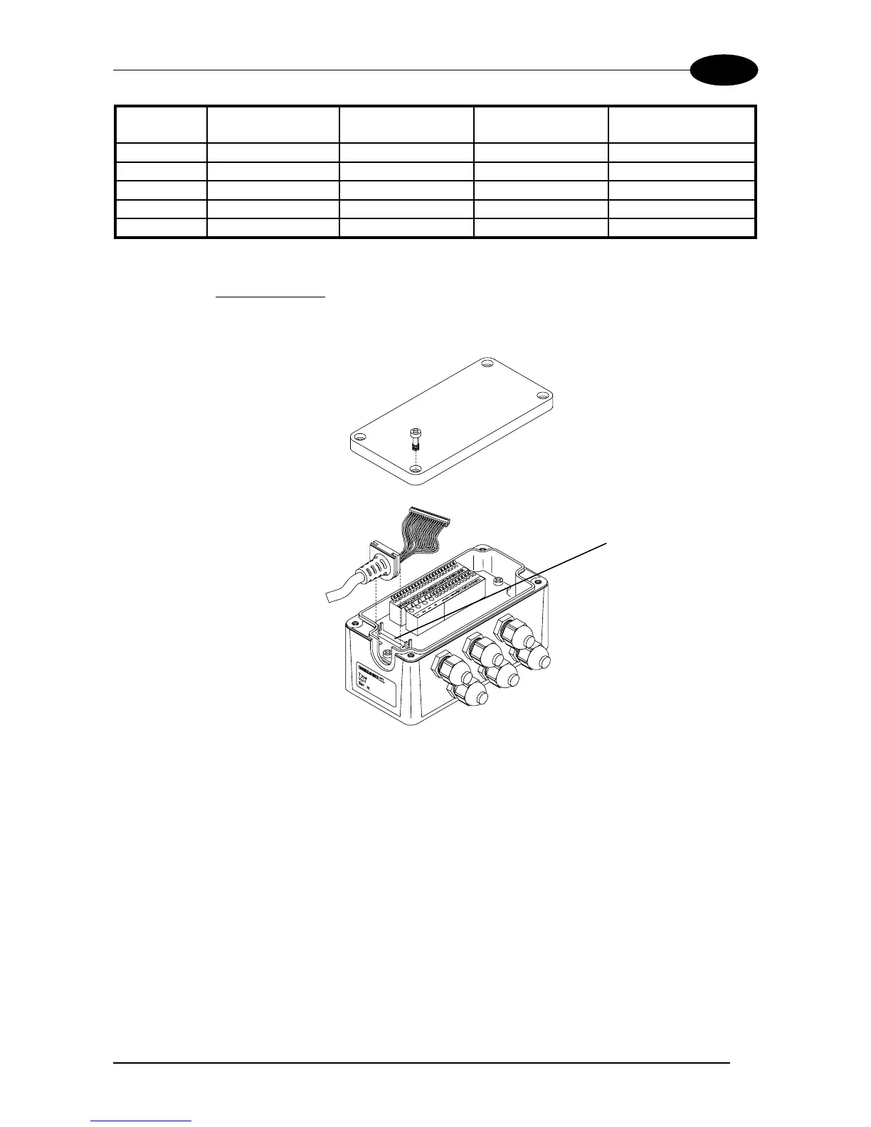
4) After wiring the junction box and while the scanner is unplugged from the power,
place the Scanner cable so that the rubber seal fits into the cutout in the housing
of the junction box and plug the 24-pin connector into connector J1 on the PCB
inside the junction box as shown in Figure 10.
Scanner cable
J1
Rubber seal
Figure 10 - Scanner cable connections to the junction box
5) Close the junction box using the 4 cover screws making sure the rubber seal is
fitted correctly between the parts of the housing.
The junction box is now installed which completes the electrical connections for your
scanning system.
If it ever becomes necessary to disconnect the scanner from the Junction Box, simply
reverse the procedure in step 4.