INSTALLATION
9
2
2.3.2 Junction Box Electrical Connections
The connection and wiring procedure for Junction Box is described as follows:
1) Open the junction box by unscrewing the 4 cover screws.
2) Pass all System cables through the glands in the junction box housing.
3) To connect the power and input/output signals:
• Prepare the individual wires of the system cables by stripping the insulation
back approximately 11 mm.
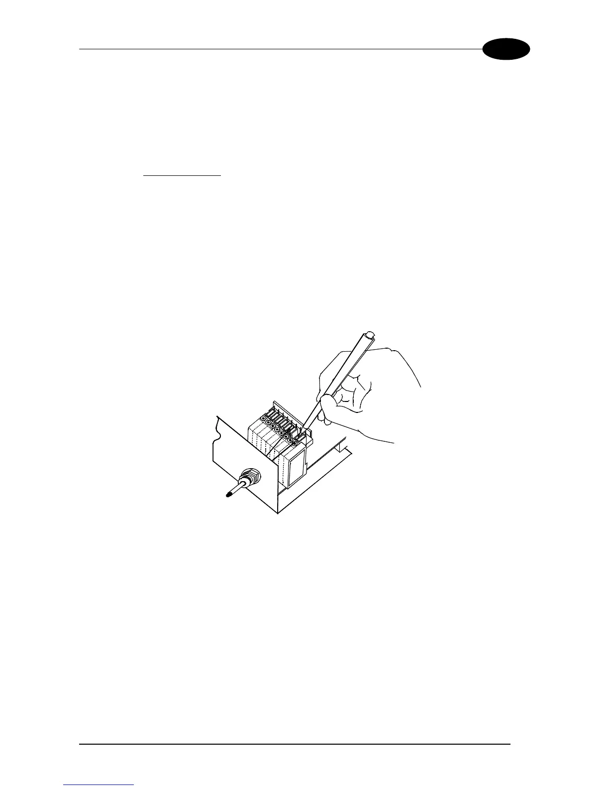
• Using a device such as a screwdriver, push down on the orange lever directly
above the clamp (see Figure 7).
• Insert the wire into the clamp and release the lever.
The wire will now be held in the spring clamp.
Figure 7 - System cable connections to the junction box
The wiring used can be solid or stranded but must meet the following specifications:
Positions 1-4: 24 - 16 AWG 0,2 - 1,5 mm
2
Positions 5-39: 26 - 20 AWG 0,14 - 0,5 mm
2
The junction box pinouts are indicated in the following table: