OUTPUTS
PRODUCT REFERENCE GUIDE 32
These inputs are optocoupled and can be driven by both NPN and PNP type commands.
Trigger and external push-button connection
The following table shows how to connect the Trigger and Remote inputs.
OUTPUTS
The three outputs can be configured as NPN, PNP, and Push-Pull (default setting). They
are short-circuit protected and the maximum load is 100 mA.
Output 2 and Output 3 serve as GOOD and NO GOOD Object signals. By default, they
stay active for 10 ms.
Output 1 serves as Data Valid signal. It is activated 1 ms after the GOOD or NO GOOD
Object signal activation, and deactivated 1 ms before the GOOD or NO GOOD Object
signal deactivation.
The output activation length can be set via Smart-VS WebApp on the Settings page.
Digital I/O diagram
Image acquisition starts on the Leading edge of the input trigger signal (default, can be
changed to Trailing edge via Smart-VS WebApp).
A Debounce time can be set on the Smart-VS WebApp to reject noisy trigger signals.
Each trigger event corresponds to a Data Valid signal indicating that the Output signals
can be sampled.
The inspection result, i.e. a GOOD or NO GOOD object detected, is always available after
the response time defined during the Teach phase.
If a Debounce time greater than zero has been set, the device response time is 50 ms
plus the trigger Debounce time.
NOTE: Polarity insensitive inputs assure full functionality even if pins A
and B are exchanged.
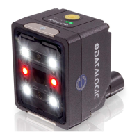
RECOMMENDED CONNECTION NOTES
External
Push-Button
A Normally Open push-button is
needed.
I2A and I2B are polarity insensitive and
can be inverted.
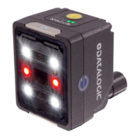
Trigger signal
from PNP device
Connect the output of the PNP trigger
device to I1A and the GND supply rail to
I1B.
I1A and I1B are polarity insensitive and
can be inverted.
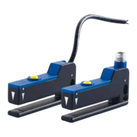
Trigger signal
from NPN device
Connect the output of the NPN trigger
device to I1B and the VDC supply rail to
I1A.
I1A and I1B are polarity insensitive and
can be inverted.