35 SMART-VS PLUS
CHAPTER 5
TYPICAL LAYOUTS
The following typical layouts refer to system hardware configurations. Dotted lines in
the figures refer to optional hardware configurations within the particular layout.
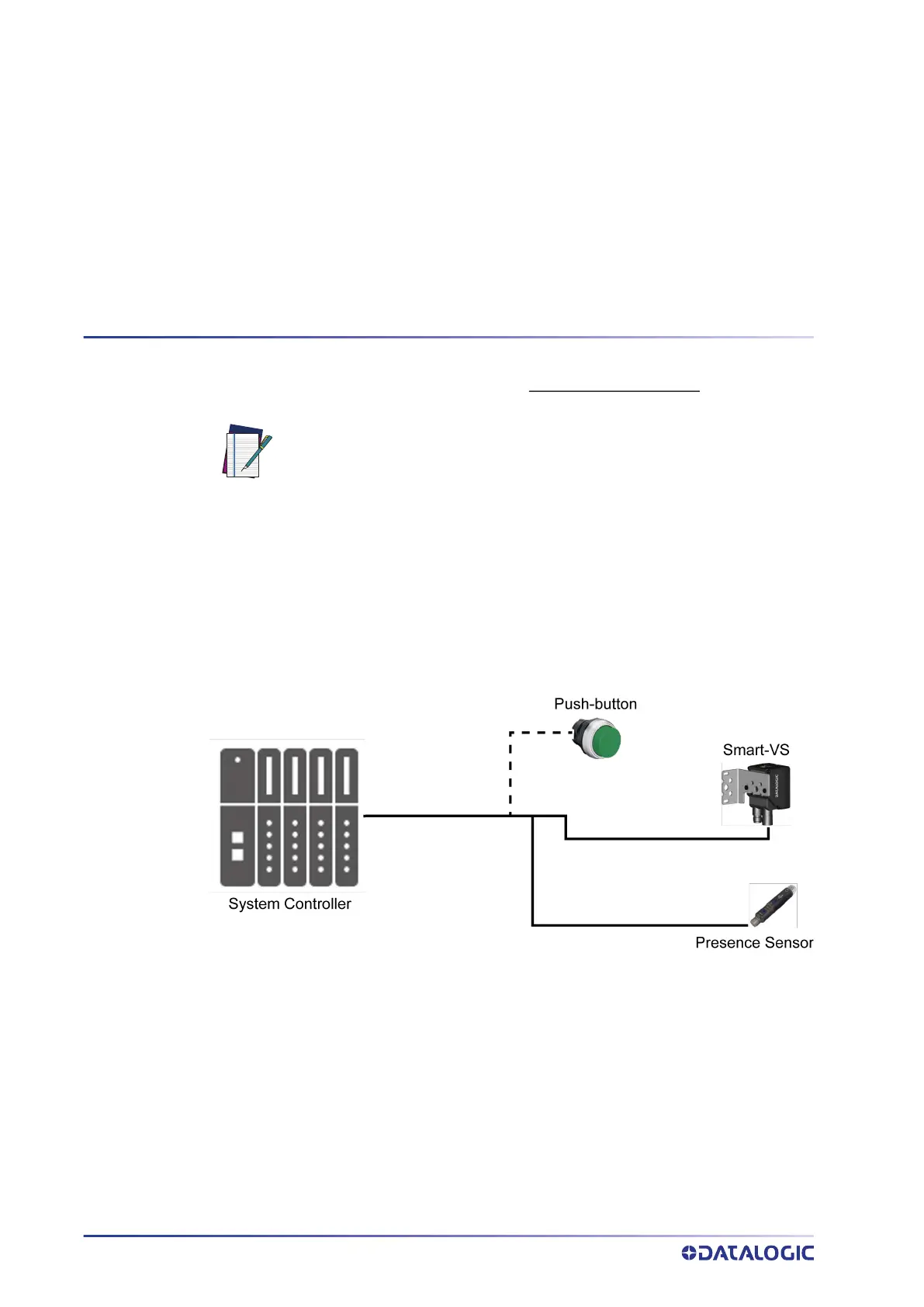
SENSOR-LIKE SETUP
The Smart-VS Plus is connected directly to the machine control system.
An optional push-button is recommended if Teaching is frequently performed for prod-
uct batch changes or if the device is not easily accessible.
A presence sensor or the machine electrical phase is necessary to trigger image acquisi-
tion.
Figure 16 - Sensor-like Setup
NOTE: All software configurations are made through the Smart-VS
WebApp, which connects to the reader through the on-board Ethernet
interface.