A-Class 89
8. Slide the Printhead Assembly completely onto the Pivot Shaft and, using the previously
removed screw and washers, secure the Printhead Assembly.
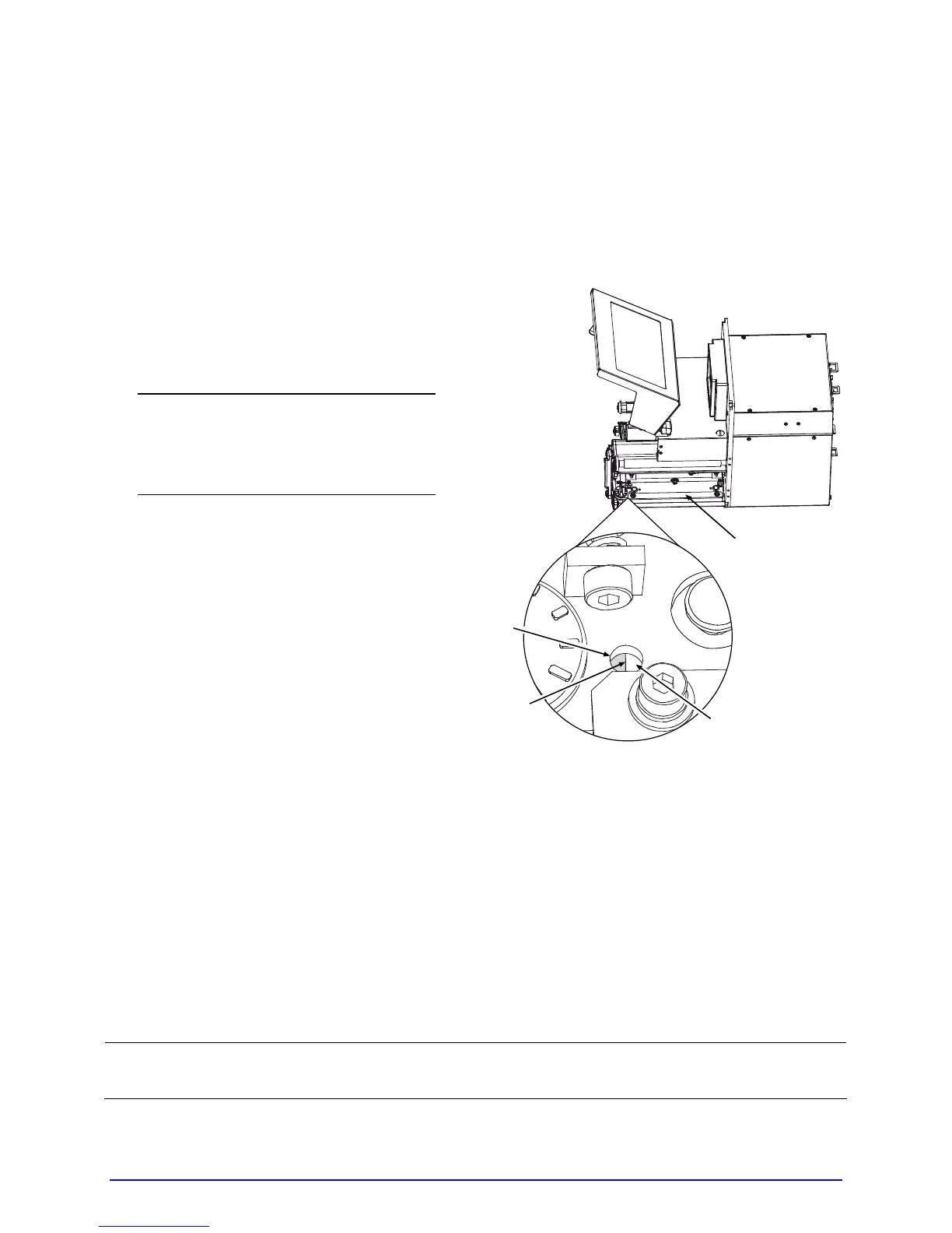
9. Place the Printhead onto the locating pins (on the underside of the Printhead Assembly).
(Use the Alignment Window in the Printhead Assembly to center the edge of the
Printhead, as shown below, and then move the Printhead forward or backward to locate
the pins.)
;
The drawing illustrates the
Alignment Window of a right
hand model printer, while left
hand models are mirrored in
orientation.
Printhead’s
Edge
Printhead
Assembly
Printhead
Alignment
Window
10. Secure the Printhead with the Captive Screw(s), but do not over-tighten.
11. Clean the Printhead using alcohol and allow it to dry; see Section 5.5.1.
12. Reload media, and ribbon (if removed), lower the Head Lift Lever into the locked
position. Plug in and turn ON the printer.
13. Print a Validation Label (see Section 4.3.4) then examine the printed label and, if
necessary, adjust the DARKNESS setting (see PRINT CONTROL / CUSTOM
ADJUSTMENTS, Section 4.2.2) to match the previously produced print contrast.
;
A replacement printhead does not typically require alignment; however, if print
quality has changed, see Section 5.3.2.