2.a.5 CONNECTING A VOLTAGE
SOURCE TO THE MODEL 3560
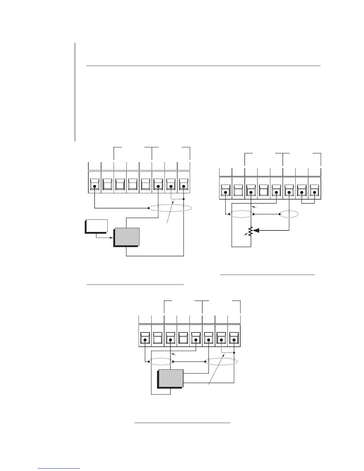
Fig. 9(a) gives standard cabling for connecting to the Model 3560 Voltage Con-
ditioner a general ANALOG SIGNAL SOURCE, floating or grounded, with its own
power supply (if required); Fig. 9(b), for connecting an EXTERNAL ZERO-TO-FULL-
SCALE POTENTIOMETER with a resistance from 2 to 10 kilohms, using the instru-
ment's ±12-V excitation; and Fig. 9(c), for connecting an EXTERNAL DC-TO-DC
LVDT, again using the ±12-V excitation. As shown in Fig. 9(a), a floating input is to
be grounded by tying the transducer's –SIGNAL line to the SIG COM terminal.
When a –SIGNAL line from the transducer is not available, the –SIG and SIG COM
terminals should be connected by a jumper wire (as in Figs. 9(b) and 9(c)).
2.6
2
SETUP: CONNECTIONS AND POWERUP
2.a TRANSDUCER CONNECTIONS:MODEL 3560
SHIELD
N/CSHLD
–SIGNAL
+SIGNAL
Reg. Power
Supply
(if required)
–
+
ANALOG
SIGNAL
SOURCE
Add wire for
floating input
POWER
OUT
SIGNAL
INPUT
± 40 MA MAX
COM
SIG
SIG
–
SIG
+
–12VCOM+12V
N/CSHLD
POWER
OUT
SIGNAL
INPUT
± 40 MA MAX
COM
SIG
SIG
–
SIG
+
–12VCOM+12V
SHIELD
+SIGNAL
–EXCITATION
2K to
10K
+EXCITATION
Fig. 9(b) Model 3560 Transducer
Cabling: External Potentiometer
N/CSHLD
POWER
OUT
SIGNAL
INPUT
± 40 MA MAX
COM
SIG
SIG
–
SIG
+
–12VCOM+12V
SHIELD
+SIGNAL
–EXCITATION
+EXCITATION
DC-to-DC
LVDT
–SIGNAL
Tie the –SIG and SIG COM
terminals if a –SIGNAL wire from
the transducer is not available
Fig. 9(c) Model 3560 Transducer
Cabling: External DC-to-DC LVDT
Fig. 9(a) Model 3560 Transducer
Cabling: General Voltage Source
 Loading...
