2.a.6 CONNECTING A DC STRAIN GAGE
TRANSDUCER TO THE MODEL 3570
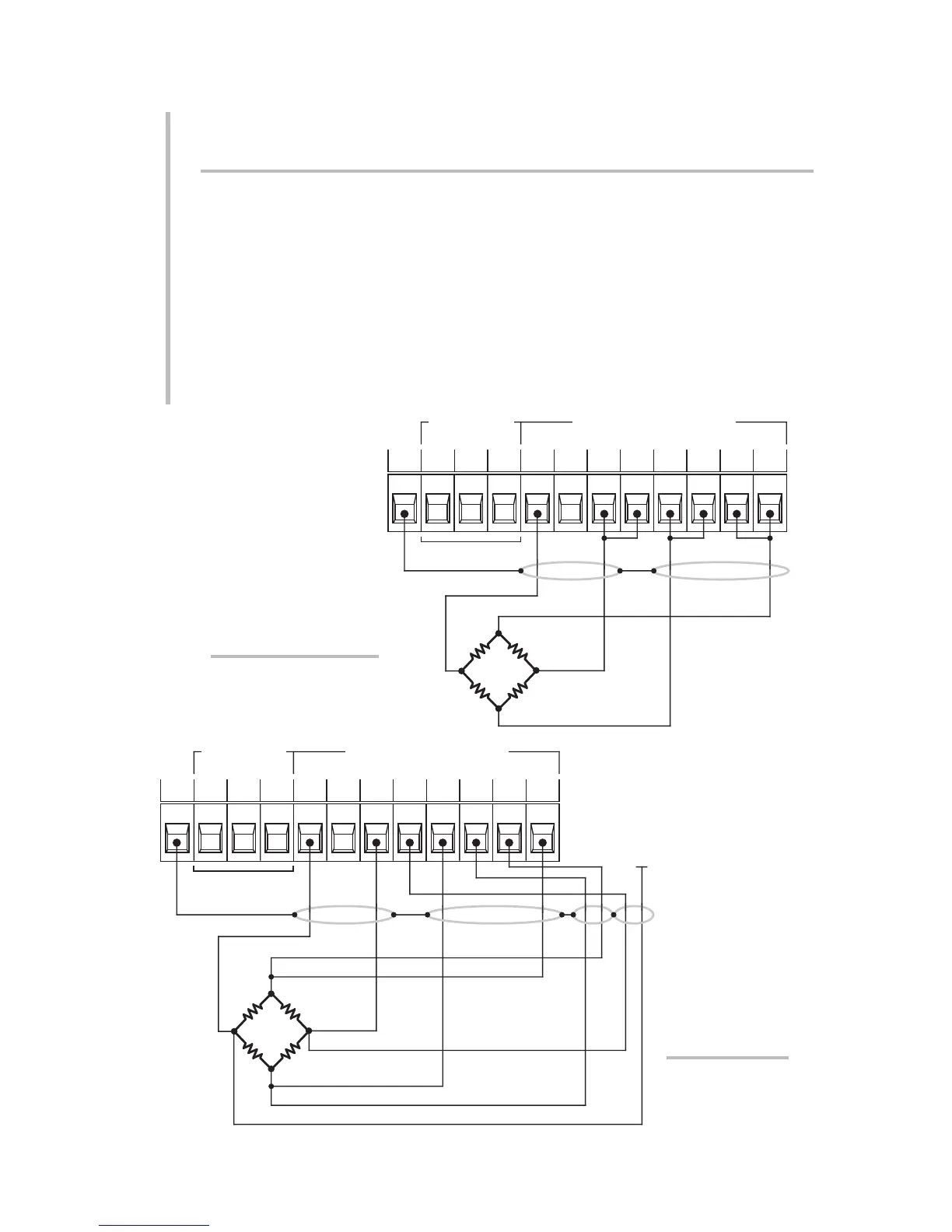
Four-wire strain gage cabling (Fig. 10(a)) is to be used with the Model 3570 DC
Strain Gage Conditioner when the cable is under 20 feet in length. In this case,
the +SENSE and –SENSE lines are tied to the corresponding EXCITATION lines,
and also the CALIBRATION SENSE line to the +SIGNAL line, at the CONDITIONER
CONNECTOR.
Eight-wire strain gage cabling (Fig. 10(b)) is to used when the cable is 20 feet or
longer. In this case, the +SENSE and –SENSE lines are tied to the corresponding
EXCITATION lines, and the CALIBRATION SENSE line to the +SIGNAL line, at the
transducer. Note also the wire connected to the –SIGNAL line at the transducer,
but left unconnected at the instrument. This wire is to be paired with the CAL
SENSE line, as shown, for shielding purposes.
2.7
SETUP: CONNECTIONS AND POWERUP
2
2.a TRANSDUCER CONNECTIONS: MODEL 3570
Fig. 10(b) Model 3570
Transducer Cabling:
8-Wire Cabling
(20 ft. or longer)
See Fig. 5(b)
–
SHLD
SHUNT CAL
CONTROL
STRAIN GAGE INPUT
SIG
+–
COM
SIG
+
EX
+
SENS
+
SENS
–
EXSENS
CAL–
SIGCOM
PWR
SHIELD
+SENSE
+EXCITATION
–EXCITATION
–SIGNAL
+SIGNAL
–SENSE
CAL
SENSE
Fig. 10(a) Model 3570
Transducer Cabling:
4-Wire Cabling
(under 20 ft. in length)
See Fig. 5(b)
–
SHLD
SHUNT CAL
CONTROL
STRAIN GAGE INPUT
SIG
+–
COM
SIG
+
EX
+
SENS
+
SENS
–
EXSENS
CAL–
SIGCOM
PWR
SHIELD
+SENSE
+EXCITATION
–EXCITATION
–SIGNAL
+SIGNAL
–SENSE
CAL SENSE
UNCONNECTED WIRE
(PAIRED WITH "CAL SENSE")
 Loading...
