26 | Installing the Switch
www.dell.com | support.dell.com
Figure 4-4. Stacking Topology Using 24G Single-port Modules
Connecting Two Switches
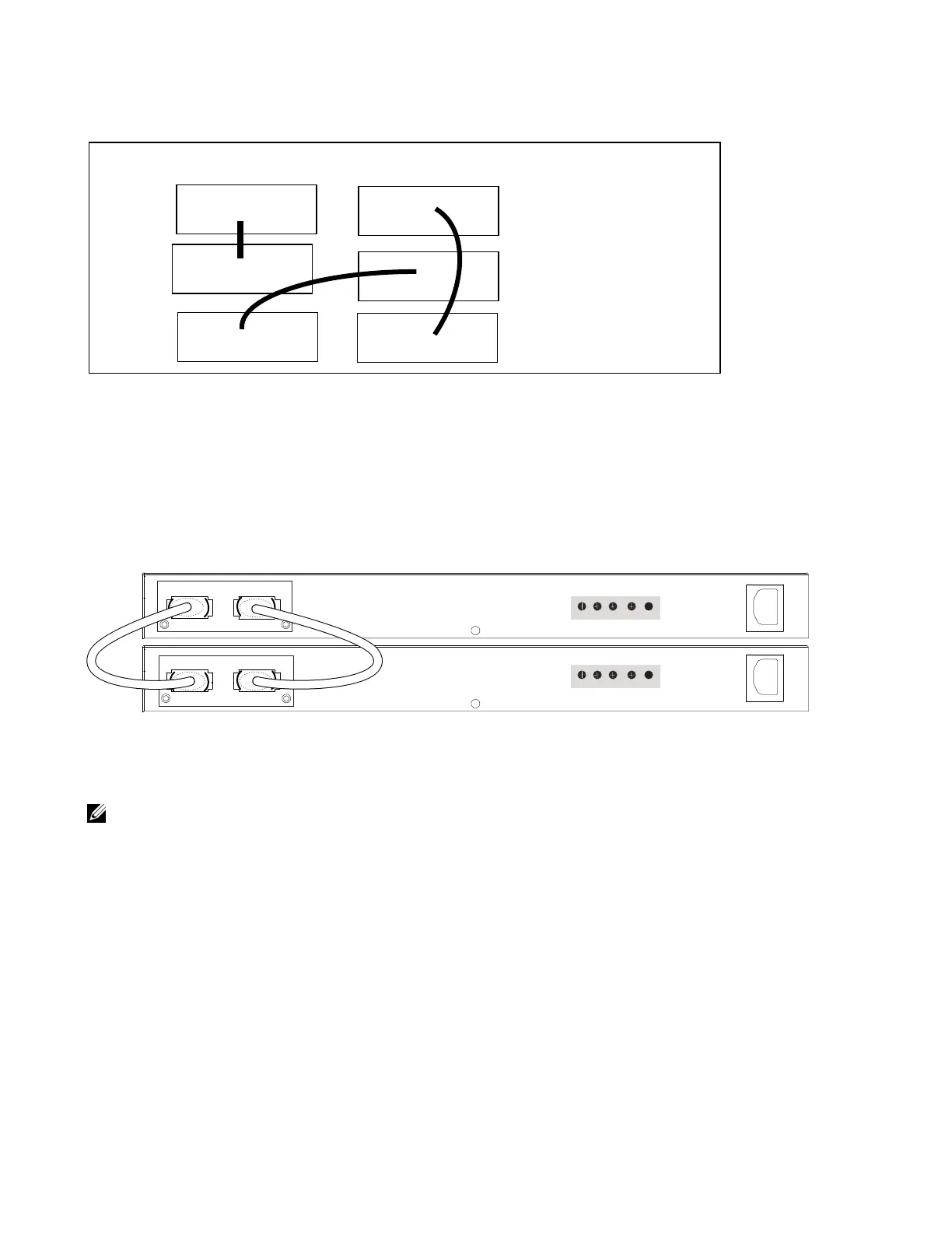
Insert one end of the special stacking cable into a stack port, and insert the other end into a stack port of
the adjacent switch. Optionally, insert a second cable into the other open stack port, as shown in
Figure 4-5
. The second cable provides both backup connectivity and increased data transfer between the
units.
Figure 4-5. Stack Ports of Two S50V Switches Connected in a Ring
NOTE: These diagrams and instructions use “Stack Port A” and “Stack Port B” for clarifying the connections,
but the modules are not labeled.
Connecting Three Switches
Dell Force10 recommends the ring topology, as outlined above (
Figure 4-3 on page 25
), for stacking S-
Series switches, providing redundant connectivity. Using the example of three switches in the stack
(
Figure 4-6
), and starting with the switch at the bottom of the stack:
• Insert one end of the first cable into Stack Port A.
• Insert the other end of the cable into Stack Port A of the middle switch.
• Insert the second cable into Stack Port B of the middle and top switches.
Switch 1
Switch 2
Module A
Switch 3
A
A
A
Ring topology
using two
B
B
Module B
24Gig modules
B
per unit
fn00151s25V1
Stack Port B Stack Port A
FG -48V -48V Current
RTN Sharing
FG -48V -48V Current
RTN Sharing
STACK STACK
STACKSTACK

 Loading...