Installing the Switch | 27
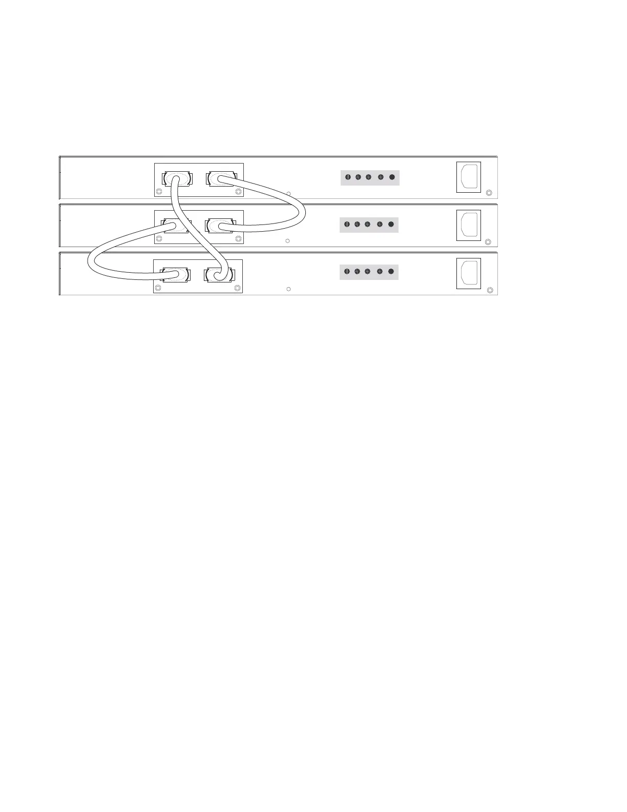
• Connect the remaining cable to the top and bottom switches by inserting one end of the cable into the
open Stack Port B of the bottom switch and the other end of the cable into Stack Port A of the top
switch.
Figure 4-6. S50V Rear View Showing Ring Topology Stacking
Supplying Power
Supply power to the switches in a stack only after they are mounted and the stack ports are connected.
There is no on/off switch, and the stack members partly determined the stack management unit from the
order in which they come on-line (see below).
The S50V and S50N switches have both AC (3-prong plug receptacle) and DC (-48V terminal-type)
connections on the back of the unit (see
Figure 2-2 on page 9
and
Figure 3-1 on page 15
). They can use
either power source independently or in combination, with the DC source in a backup mode (except for
the 470W DC power supply, as noted in the section
Power on page 14
). In other words, you have three
options for providing power to the switch — AC only, DC only, or using both AC and DC sources. If you
select the third choice — AC and DC — the switch will only use the DC source after the AC source fails.
In addition, Dell Force10 provides, as an option, an external DC Redundant Power Supply Unit (PSU),
which has an AC input and a cable for connecting the PSU to the DC terminal leads on the switch. To
connect the switch to a DC power supply, refer to
Chapter , Installing Backup Power, on page 29
. For PoE
use, see
Connecting S50V Ethernet Ports with PoE on page 42
.
For the S50V and S50N, to use AC only, connect the supplied AC power cord first to the switch
(receptacle on the right as you face the rear of the chassis) and then to the power source (see
AC Power
Requirements on page 48
). Connect the plug to the AC receptacle at the right rear of the switch, making
sure that the power cord is secure.
S50N-DC
As shown in the section
Power on page 14
in the Site Preparation chapter, S50N-DC switches have two
terminal blocks on the right side (instead of an AC receptacle) for two DC power supply inputs. The
terminal block on the right, as you face the back of the chassis, is matched to the DC1 status LED on the
STACKSTACK
STACKSTACK
STACKSTACK
fn00152s50V1
Stack Port A Stack Port B
FG -48V -48V Current
RTN Sharing
FG -48V -48V Current
RTN Sharing
FG -48V -48V Current
RTN Sharing

 Loading...