NOTE: For models shipped with a USB Type-C port, a USB Type-C bracket is secured to the system board with single
(M2x3.5) screw. The bracket is bundled with the system board as a service part and MUST NOT be removed from the
system board.
4. Remove the single (M2x2) screw that secures the system board to the palm-rest.
5. Carefully lift the system board away from the chassis.
Installing the system board
Prerequisites
If you are replacing a component, remove the existing component before performing the installation process.
About this task
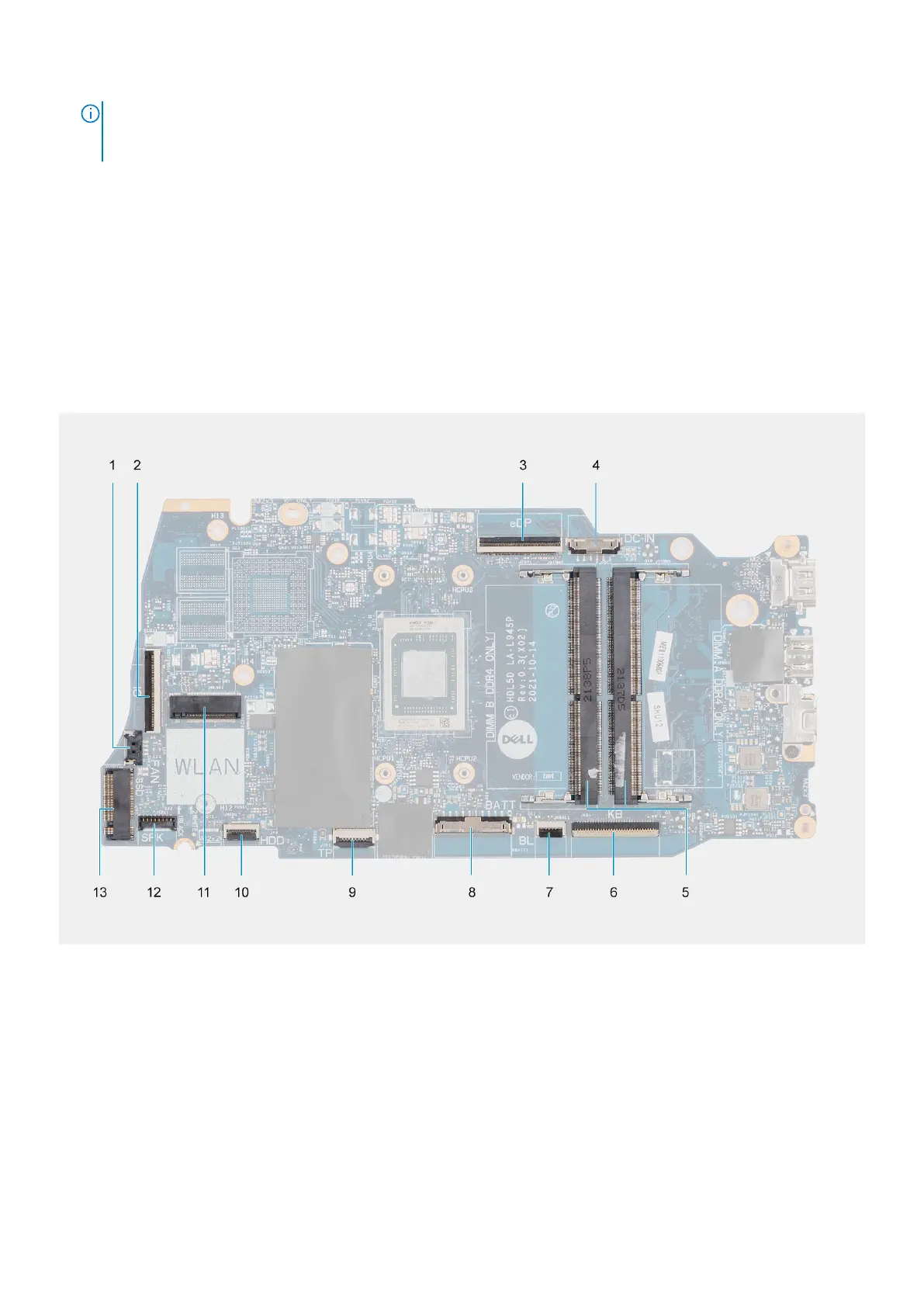
The following image indicates the connectors on your system board:
1. Fan connector 2. I/O board FFC connector
3. eDP connector 4. DC-in port connector
5. Memory modules 6. Keyboard FFC connector
7. Keyboard-backlight FFC connector 8. Battery connector
9. Touchpad FFC connector 10. Hard drive FFC connector
11. Wireless connector 12. Speaker cable connector
13. Solid-state drive connector
The following images indicate the location of the system board and provide a visual representation of the installation procedure.
82
Removing and installing components