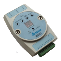
Ethernet Communication Module IFD9506
DVP-PLC Operation Manual
4 Monitoring Functions
The values in the device monitoring tables and monitored statuses can be read by monitor registers.
The monitored-device tables are set in DCISoft.
4.1 Monitor Bit Registers (MB)
Ethernet Communication Module: IFD9506
0~250 Reserved
251~263 R Monitored value
Every MB records the value in the 16-bit
0
No
264~270 R Monitored status
Every MB records the status in the 16-bit
device.
0
No
Symbol “R” refer to read only; “R/W” refers to read and write.
MB251: Monitored Value
Explanations:
Every MB records the values in the 16-bit device.
b15 b14 b13 b12 b11 b10 b9 b8 b7 b6 b5 b4 b3 b2 b1 b0
16
15
14
13
12
11
10
9
8
7
6
5
4
3
2
1
MB264: Monitored Status
Explanations:
Every MB records the status in the 16-bit device. 1: normal; 0: abnormal.
b15 b14 b13 b12 b11 b10 b9 b8 b7 b6 b5 b4 b3 b2 b1 b0
16
Device
15
14
13
12
11
10
9
8
7
6
5
4
3
2
1
4.2 Monitor Word Registers (MW)
Ethernet Communication Module: IFD9506
0-250 Reserved
251~350 R Monitored value
Every MW records the monitored value in 1
register.
0
No
351~357 R Monitored status
Every MW records the status in a 16-bit
register.
0
No
Symbol “R” refer to read only; “R/W” refers to read and write.

 Loading...