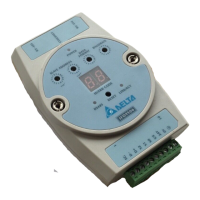
Ethernet Communication Module IFD9506
DVP-PLC Operation Manual
2.5 RJ-11 Pin Definition
RJ-11 sketch Pin Signal Definition
1 -- N/C
2 -- N/C
3 D+ Positive pole for data
4 D- Negative pole for data
5 GND Ground
6 -- N/C
2.6 RJ-45 Pin Definition
RJ-45 sketch Pin Signal Definition
1 Tx+ Positive pole for data transmission
2 Tx- Negative pole for data transmission
3 Rx+ Positive pole for data receiving
4 -- N/C
5 -- N/C
6 Rx- Negative pole for data receiving
7 -- N/C
8 -- N/C
2.7 RS-232 Pin Definition
Pin Signal Definition
1 -- N/C
2 -- N/C
3 -- N/C
4 Rx Reception data
5 Tx Transmission
6 -- N/C
7 -- N/C
8 GND Ground
2.8 Node Address
The node address setting here is the node address of IFD9506 itself. DO NOT duplicate it with the node
address of the device connected to the RS-485 port. When IFD9506
is in normal operation, the node address
will be displayed on the message display. It is suggested you use the rotary switches to set the node address of
IFD9506. For the module with firmware V2.04 or earlier, the settings in the software are not latched when the
power is off. If the setting in the software is inconsistent with the rotary switch setting, then the rotary switch
setting will be applied after the power is on again.
For the module with firmware V2.06 or later, when the node address is set to 0x00 with the rotary switches, all
the software settings can be used and all parameters will retain the last setting values in the software after the
power is on again.

 Loading...