Ethernet Communication Module IFD9506
DVP-PLC Operation Manual
Ethernet/IP parameters setting
Service data
Modbus instruction
(High and Low bytes inverted)
Function codes
supported
0x03 Read holding registers
0x06 Write a single holding register
7.3 Ethernet/IP Operation through Implicit Message
As Ethernet/IP master, AS300 reads the serial slave data through device mapping.
Steps
1. Set up the rotary switches of IFD9506;
2. Set the device monitoring tables in DCISoft;
3. Start the project in ISPSoft;
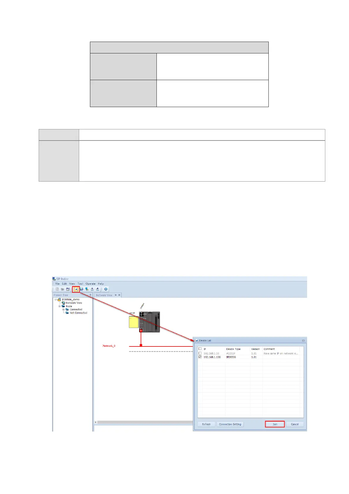
4. Start EIP Builder and add IFD9506 to the network.
1. Set
the parameters of IFD9506 with the rotary switches. Ensure that the data format and baud rate of
IFD9506 are the same as those of the serial slave and the station address is different from that of the seria
l
s
lave.
2. Connect IFD9506 to the Modbus slave of the serial terminal, start DCISoft, and ensure that IFD9506 has
been set to the serial master mode.
3. Refer to Section 5.4 Monitoring Settings, open the device monitoring table page Monitor, select Bit device o
r
Wo
rd device page, and fill in the correct station address of the slave, Modbus start address and data lengt
h
t
o be read. With a click on “Apply” button, the software will start monitoring devices automatically.
4. Start ISPSoft, enter EIP Builder (refer to AS Series Operation Manual for details on operation), scan the
network, and add IFD9506 to the network. Press the red dot on the device icon and meanwhile drag it to the
network location to make the connection.