Ethernet & Sequencer Programming SM15K
12 / 44 DELTA ELEKTRONIKA B.V. rev. Aug. 2019
The result will be in Watt Hour (Wh), scientific notation.
If the instrument is not enabled, the result will be zero.
To read the total Watt Hour for the negative power:
Syntax: MEASure:INStrument<sp>WH,NEG,TOTAL?<term>
The result will be in Watt Hour (Ah), scientific notation.
If the instrument is not enabled, the result will be zero.
To read the minimum positive power during the time the instrument is enabled:
Syntax: MEASure:INStrument<sp>WH,POS,PMIN?<term>
The result will be in Watts. If the instrument is not enabled, the result will be zero.
To read the maximum positive power during the time the instrument is enabled:
Syntax: MEASure:INStrument<sp>WH,POS,PMAX?<term>
The result will be in Watts. If the instrument is not enabled, the result will be zero.
To read the minimum negative power during the time the instrument is enabled:
Syntax: MEASure:INStrument<sp>WH,NEG,PMIN?<term>
The result will be in Watts. If the instrument is not enabled, the result will be zero.
To read the maximum negative power during the time the instrument is enabled:
Syntax: MEASure:INStrument<sp>WH:NEG,PMAX?<term>
The result will be in Watts. If the instrument is not enabled, the result will be zero.
Measure temperature
To read the highest internal temperature of the power supply:
Syntax: MEASure:TEMperature?<term>
The answer is in degrees Celsius..
5.4 Calibrate Subsystem
5.4.1 Introduction
The calibration of the power supply is done during production. However, periodical check and calibration is
recommended. At power-on, the calibration settings are restored.
There are four parameters to calibrate. Two related to the voltage measurement and two related to the
current measurement.
For proper calibration it is recommended to use the following order (an SM500-CP-90 is used as example) :
- Set output voltage of the power supply to e.g. 1% of the maximum output voltage.
SOURce:VOLtage<sp>5.00<term>
- Calibrate the measure voltage offset, so the result of the command MEASure:VOLtage? is as
close as possible to 5.00 V.
- Set the output voltage to maximum
SOURce:VOLtage<sp>500<term>
- Calibrate the measure voltage gain, so the result of the command MEASure:VOLtage? is as
close as possible to the actual output voltage, 500 V.
Same principle is used for the current calibration.
Default settings for the offsets are 0, and default settings for the gains are 1. The resolution of both settings
and readings are 6 digits.
Notice: Both gain and offset changes influence the actual output parameter. After changing offset, check if
the gain has to change. And visa versa. To get a very accurate result, redo the calibration a few times. To
save the calibration settings to the non-volatile memory, refer to section 5.1
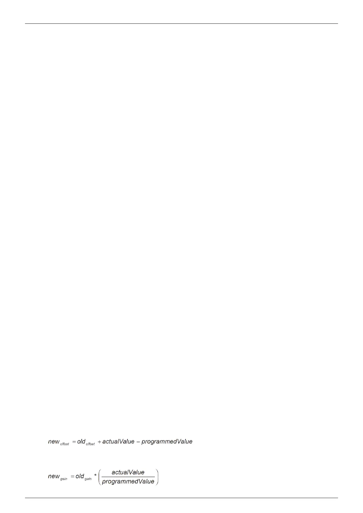
For MEASURE offset calibration, use the equation:
For MEASURE gain calibration, use the equation:
 Loading...


