Ethernet & Sequencer Programming SM15K
37 / 44 DELTA ELEKTRONIKA B.V. rev. Aug. 2019
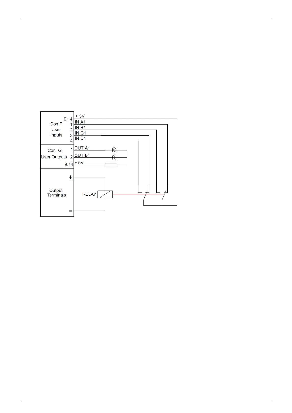
6.6.2 Example 2: Test relays.
To test the double-pole contacts of relays and the working voltage of their coils (specified between 6 and
11.8V), the output voltage of the power supply ramps from 5 to 12 Volt. At 5V, the output current must be
higher than 10mA, otherwise the test doesn't start.
Contacts are tested open and closed. When the relay switches, the working voltage must be checked.
The results are indicated via a red or a green LED.
Wiring diagram: Programming steps:
1 oa1=0
2 ob1=0
3 js 20
4 nop
5 w=1
6 sv=5.9
7 cjne ia1,1,30
8 cjne ib1,0,30
9 cjne ic1,1,30
10 cjne id1,0,30
11 cjg sv,11.8,30
12 inc sv,0.05
13 w=0.1
14 cjne ia1,1,34
15 cjne ib1,0,34
16 cjne ic1,1,34
17 cjne id1,0,34
18 jp 11
19 end
20 sv=5
21 sc=0.3
22 sp=25
23 w=0.1
24 cjg mc,0.01,29
25 oa1=1
26 ob1=1
27 w=1
28 jp 19
29 ret
30 oa1=1
31 w=1
32 jp 19
33 nop
34 ob1=1
35 w=1
36 jp 19
37 nop
 Loading...


