Ethernet & Sequencer Programming SM15K
4 / 44 DELTA ELEKTRONIKA B.V. rev. Aug. 2019
1 In General
1.1 Features
The Remote Ethernet programming function is an interface between a TCP/IP network and the Power
Supply. It allows the operator to create fully automated systems. The Ethernet interface can set and
measure the parameters of the power supply, read the status signals, set controls, interacts with digital I/O
and generate waveforms, stored in memory. It is even possible to take over tasks from a PLC. That makes
processes and test systems more powerful and less complex.
1.2 Analog
The power supplies of Delta Elektronika are very stable and accurate. The Ethernet interface is designed
especially for these kinds of power supplies. Therefore the programming and measuring resolution is 16
bits and all units are calibrated very precisely by the factory. To calculate the step size in (Voltage or
Ampere) use the equation below:
To calculate the stepsize in Watt use the equation below:
1.3 Status
The power supplies are equipped with a lot of signals which inform the user about the status of the supply.
Status like Limit, OverTemperature, DCF, etc. can be read to check the condition of the system.
For example, ACF-signal (which indicates an incorrect input voltage) can be monitored, so action can be
taken to avoid problems before a system is switched off.
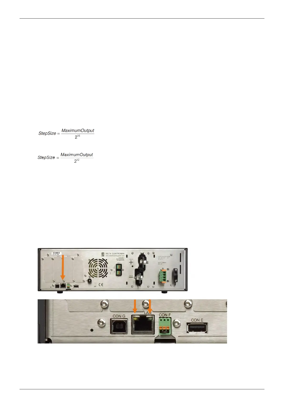
1.4 LEDs
Next to the RJ45 connector are two LEDs, see picture below.
The left orange LED is named "ERR". When this LED is ON, the Ethernet interface has generated an error
message as a result of a bad command or parameter.
The right Green LED is named "LNK/ACT", which stands for Link/Activity. This LED indicates whether or
not the Ethernet interface is connected and communicates.
 Loading...


