AS Series Module Manual
5- 10
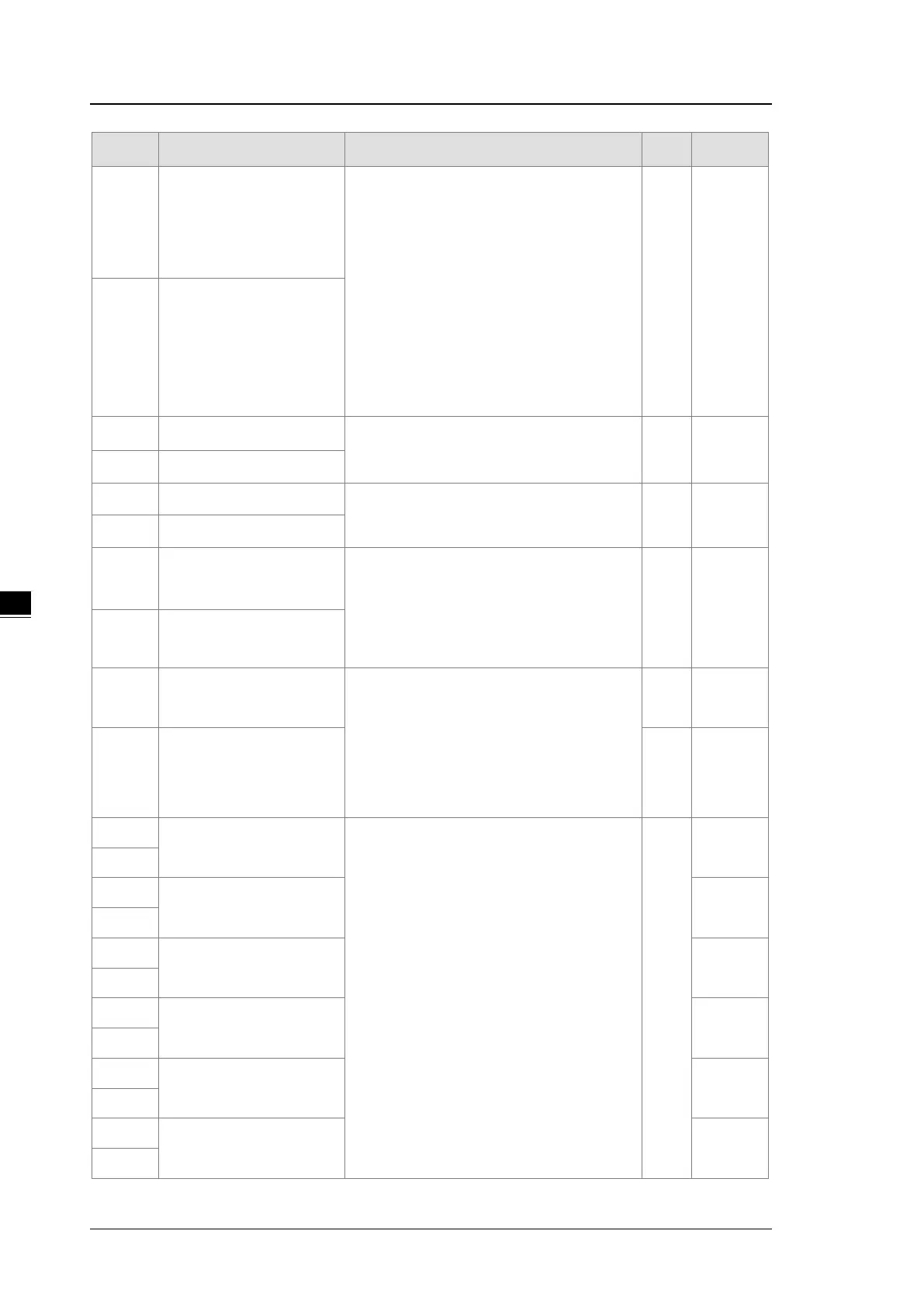
CR# Name Description
Atr. Defaults
23
setup
0: closed
1: -10 V to +10 V (default)
2: 0–10 V
3: -5 V to +5 V
4: 0–5 V
5: 1–5 V
6: 0–20 mA
7: 4–20 mA
R/W
1
24
setup
25
Output channel 1 offset
Range: -32768 to +32767
R/W 0
26
Output channel 2 offset
27
Output channel 1 gain
Range: -32768 to +32767
R/W 1000
28
Output channel 2 gain
29
Retain the output sent by
channel 1
0: When the PLC stops, the value of the
analog output is reset to 0.
1: When the PLC stops, the value of the
analog output is retained.
R/W 0
30
Retain the output sent by
channel 2
31
output sent by channel 1
Range: 10–3200 (100 ms–32000 ms)
Unit: 10 ms
Any value less than 10 is read as 0. Any value
larger than 3200 is read as 3200.
Set the value to 0 to disable this function.
R/W 0
32
Refreshing the time for an
output sent by channel 2
R/W 0
33
The minimum scale range
for input channel 1
When the format is
HWCONFIG, the scale range is invalid.
For analog-digital modules, it is much more
convenient if the system can convert digital
values to floating-
understanding. Here you can set the minimum
and maximum scale ranges of corresponding
floating-point values for channels.
For example, if the scale range for an analog
to digital input channel is ±
10.0 V, it indicates
the maximum value is +10.0 V and the
minimum value is -10.0 V.
R
-10.0
34
35
The minimum scale range
for input channel 2
-10.0
36
37
The minimum scale range
for input channel 3
-10.0
38
39
The minimum scale range
for input channel 4
-10.0
40
41
The minimum scale range
for output channel 1
-10.0
42
43
The minimum scale range
for output channel 2
-10.0
44
 Loading...