Chapter 3 Analog Input Module AS04/08AD-A
3- 17
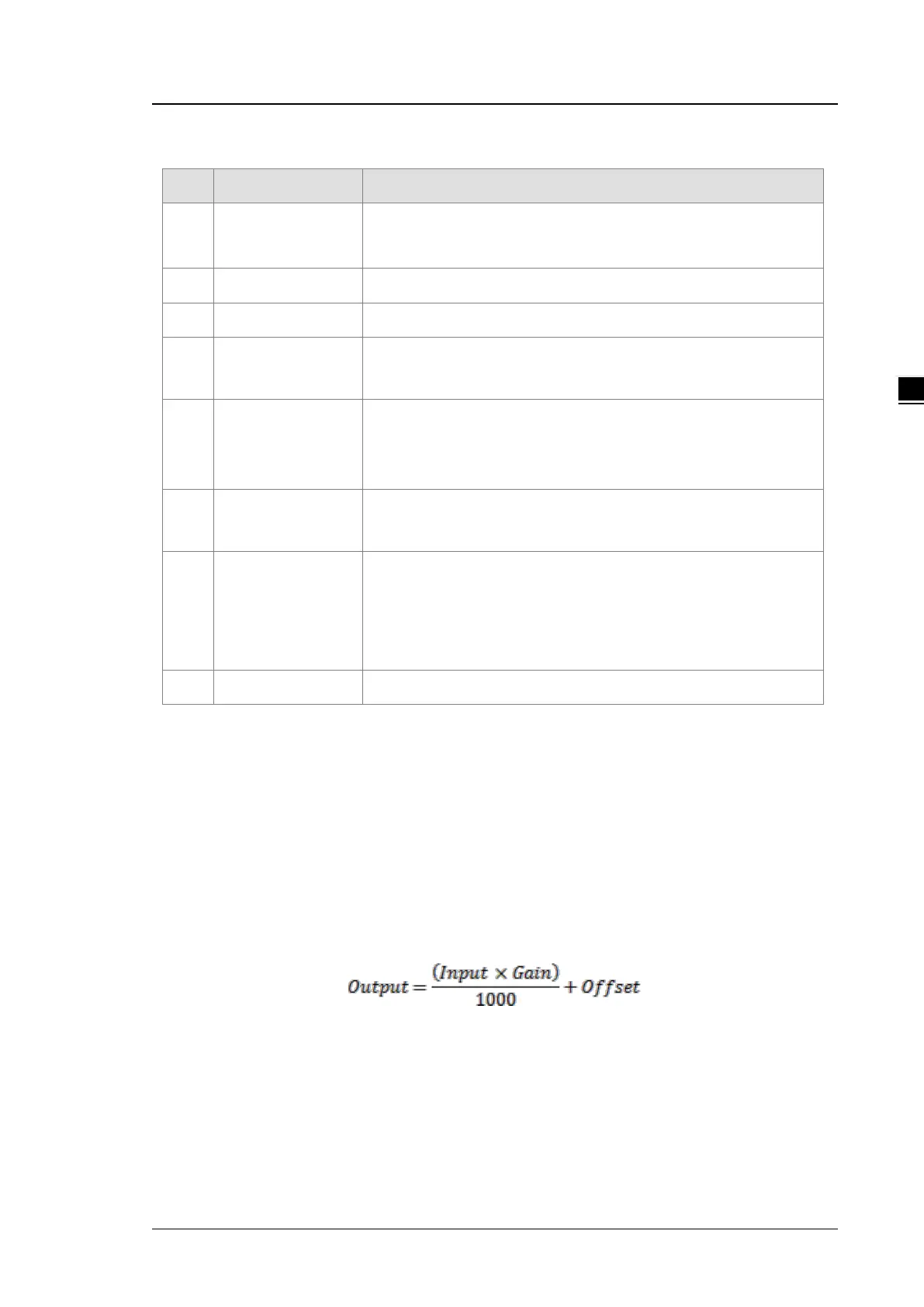
3.2.6 Functions
Item Function Description
1
Enable/Disable a
Channel
1. Enable or disable a channel.
2. If a channel is disabled, the total conversion time decreases.
2 Calibration Calibrate a linear curve.
3 Average Conversion values are averaged and filtered.
4
Disconnection
Detection
Disconnection detection only operates when the analog range is 4 mA–
20 mA or 1 V–5 V.
5
Channel Detect and
Alarm
If an input signal exceeds the range of inputs that the hardware can
receive, the module produces an alarm or a warning. You can disable
this function.
6
The Limit Detections
for Channels
Save the maximum/minimum values for channels.
7
Records for
Channels
(Applicable for
AS04AD)
Save the analog curves for channels
8 Scale Range When the format is floating-point, you can set the scale range.
1. Enable/Disable a channel
An analog signal is converted into a digital signal at a rate of 2 ms per channel. The total conversion time is
2 ms X (the number of channels). If a channel is not used, you can disable it to decrease the total
conversion time.
2. Calibration
To make a curve meet specific needs, calibrate the curve by changing the offset and the gain. The
calibration range depends on the range of inputs that the hardware can receive. The formula is:
Example:
A channel receives voltage inputs between -10.0 V to +10.0 V. The gain is 1000, and the offset is 0. The
corresponding value for the original signal -10.0 V to +10.0 V is -32000 to +32000. If you change the offset to -
100, the calibrated value for the original signal -10.0 V to +10.0 V becomes -31900 to +32100.