AS Series Module Manual
4- 8
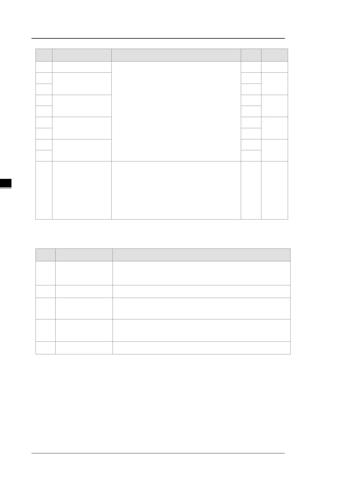
CR# Name Description
Atr. Defaults
28
range for channel 4
For example, if the scale range for an analog to digital
input channel is ±10.0 V, it indicates the maximum
value is +10.0 V and the minimum value is -10.0 V.
If the scale range for an analog to digital input channel
is 4 mA ~ 20 mA. It indicates the maximum value is 20
mA and the minimum value is 4 mA.
Note: You can use PLC instruction DSCLP (API0217)
and set SM685 to ON to use floating-point operations
when a conversion range needs to edit.
R
29
range for channel 1
R
10.0
30 R
31
The maximum scale
range for channel 2
R
10.0
32 R
33
range for channel 3
R
10.0
34 R
35
range for channel 4
R
10.0
36 R
37
Channel alarm setup
0: warning
1: alarm
bit0: error in the power supply
bit1: error in the module hardware
bit2: error in calibration
R/W 0
4.2.5 Functions
Item Function Description
1
Enable/Disable a
Channel
1. Enable or disable a channel.
2. If a channel is disabled, the total conversion time decreases.
2 Calibration Calibrate a linear curve.
3
Retain an Output
When a module stops running, the system can retain the signal sent by the
module.
4
Refresh Time for an
Output
Refresh the analog output value according to the value of the fixed slope.
5 Scale Range You can set the scale range when the format is floating-point.