AS Series Module Manual
2- 4
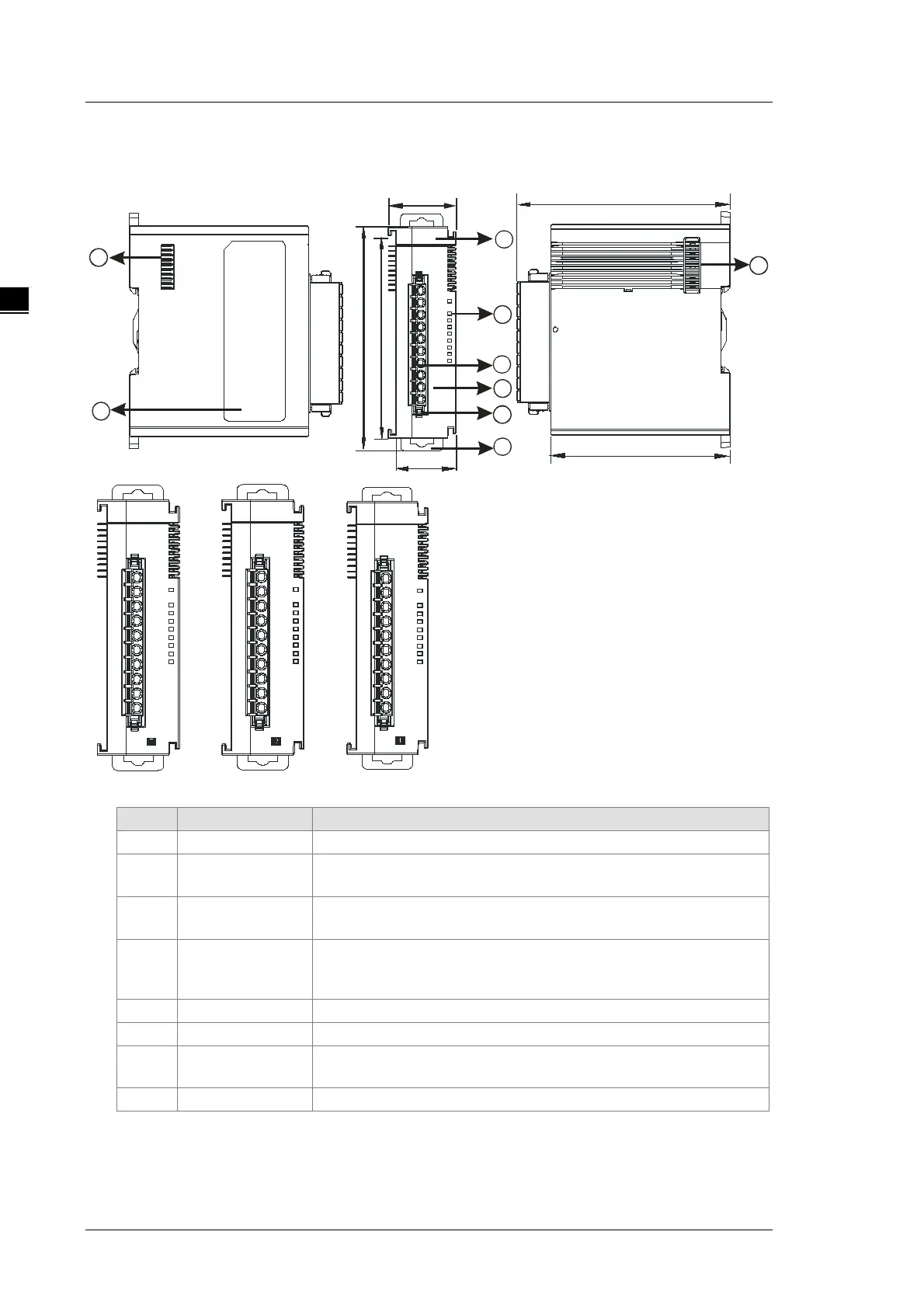
2.1.2 Digital Input/Output Module Profiles
AS08AM10N-A/AS08AN01P-A/AS08AN01R-A/AS08AN01T-A
28.2
25
88
98.3
1
4
5
3
6
7
8
89
75
7
08AM
5
6
7
2
3
6
5
4
3
4
7
PWR
0
1
2
1
0
IN
IN
S/S
S/S
5
6
7
2
3
4
0
1
IN
S/S
S/S
2
08AN
6
5
4
3
7
PWR
OUT
0
2
1
OUT
4
7
6
5
3
2
1
0
C0
C0
08AN
6
5
4
3
7
PWR
OUT
0
2
1
C0
C0
OUT
4
5
6
7
1
2
3
0
08AN
3
4
5
6
7
PWR
OUT
0
2
1
OUT
4
7
6
5
3
2
1
0
C0
C0
Unit: mm
2
Input/output LED
indicator
If there is an input signal, the input LED indicator is ON.
If there is an output signal, the output LED indicator is ON.
3
block
The inputs are connected to sensors.
The outputs are connected to loads to be driven.
4
Arrangement of the
input/output
Arrangement of the terminals
Secures the terminal block
6 DIN rail clip Secures the DIN rail
7
External module
port
Connects the modules