Chapter 9 Serial Communication Module AS00SCM
9- 9
9.3 COM mode
This section introduces communication modes of AS00SCM-A module (firmware V2.00) when the communication
protocol is Modbus, UD Link or CANopen.
9.3.1 Modbus
The AS00SCM-A supports standard communication protocols such as Modbus RS232, RS422, and RS485. Once
you create a data exchange table, you can exchange data with slave modules.
You can set up communication format and node ID via HWCONFIG. Refer to section 9.2.3 for more details.
When AS00SCM-A acts as scanner/master, you can create a data exchange table and exchange data with
slave modules. To initialize Modbus communication: Open ISPSoft. -> HWCONFIG -> Set up the node ID and
communication format. -> Create a data exchange table. -> Select a Mode (Program Control, PLC Run, or
Always Enable). -> Download HWCONFIG. -> Enable data exchange. Refer to section 9.3 in AS Series
Operation Manual for more details.
When you use HWCONFIG to scan the modules, the data exchange table of AS00SCM-A can NOT be copied
back to HWCONIG. If you need the data exchange table of AS00SCM-A, you can use Upload on the tool bar
to send the data exchange table of AS00SCM-A back to HWCONFIG.
When AS00SCM acts as adapter/slave, it provides a communication channel for AS series PLC to read and
write.
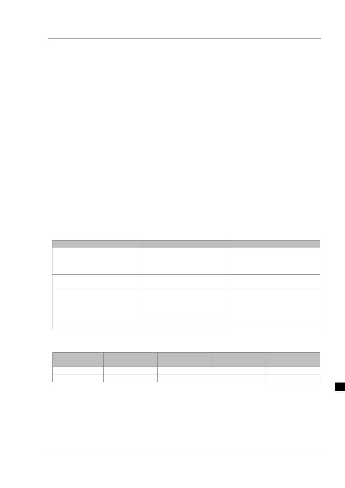
Supporting function codes and addresses are shown below.
0x03
0x04
Read
16#0100~16#0163
16#0200~16#0263
0x10
Write
16#0200~16#0263
0x17
Read
16#0100~16#0163
16#0200~16#0263
Write
16#0000~16#0063
16#0200~16#0263
Addresses and corresponding registers for function card 1 / 2
Address for data
to be written
Length (character)
Address for data
to be read
Length (character)
Corresponding data registers can be obtained when AS series PLC uses AS00SCM-A for communication and
via HWCONFIG to set up. Refer to section 9.6.1 for more details.