AS Series Module Manual
2- 2
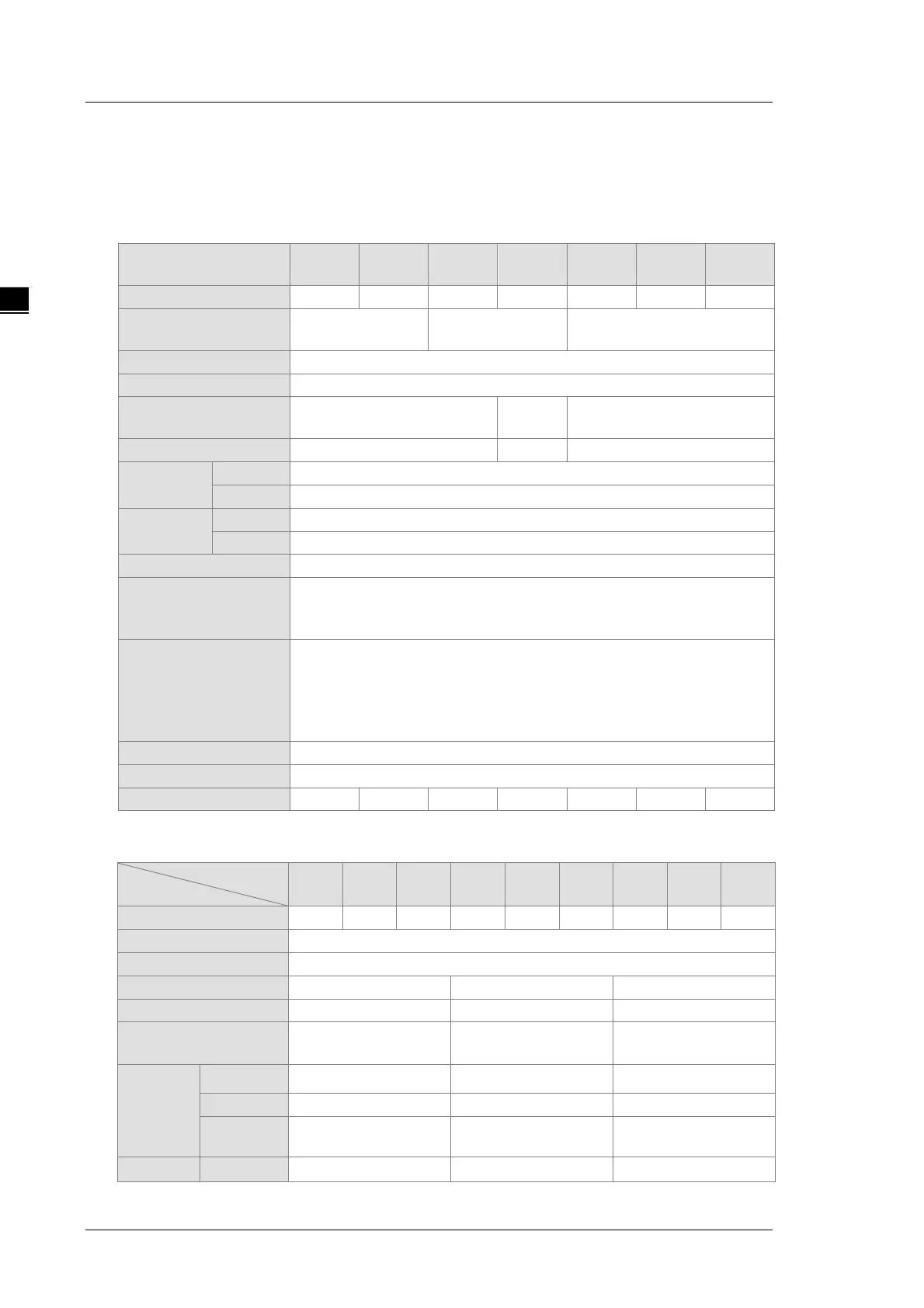
2.1 Digital Input/Output Module Specifications
2.1.1 General Specifications
Electrical specifications for the inputs on digital input/output modules
(The signals passing through the inputs are 24 VDC signals.)
Module name
08AM10N
32AM10N
64AM10N
16AP11R
16AP11T
16AP11P
Connector type
MIL connector Removable terminal block
Direct current (sinking or sourcing)
Input voltage/ current
24 VDC,5 mA
24 VDC
24 VDC,5 mA
Action level
>15 VDC
Response
time
Setting range: 0 ~ 25 ms; default: 10 ms
Maximum input
frequency
Varies according to the filter time; for example when the filter is 1 ms, the
maximum input frequency is 500 Hz, when 2 ms, 250 Hz.
Note: CPU scan time also affects the maximum input frequency.
Input signal
Voltage input
Sinking: The inputs are NPN transistors whose collectors are open
collectors.
Sourcing: The inputs are PNP transistors whose collectors are open
collectors.
When the optocoupler is driven, the input LED indicator is ON.
Electrical specifications for the outputs on a digital input/output module
Model
08
R-A
R-A
16AP11
R-A
08
T-A
T-A
T-A
P-A
P-A
16AP11
P-A
Removable terminal block
Digital output
Relay-R Transistor-T (sinking) Transistor-P (sourcing)
*2
*2
Leakage current
0uA <10uA
<250uA (@V1.00A0)
Maximum
load
Resistance
2A/output, 8A/COM
0.5A/output, 4A/COM 0.5A/output, 4A/COM
*2
Bulb
20 W (24 VDC)
2 W (24 VDC) 2 W (24 VDC)
1 Hz 100 Hz 100 Hz