AS Series Module Manual
9- 4
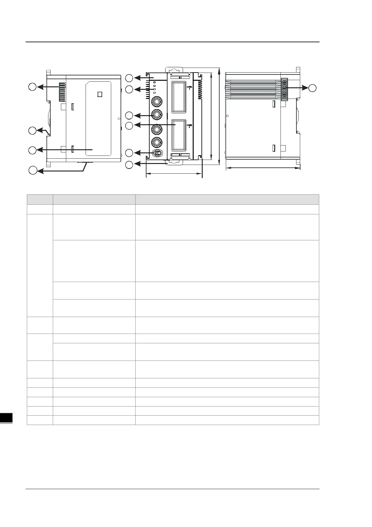
9.2.2 Dimensions and Profile
1
4
5
2
6
75
98 .3
88
56
3
7
8
9
7
10
SCM
PO WER
CA RD 1
CA RD 2
ER RO R
F OR MA T 2
C OM . RTU
ID 2
FOR M AT 1
ID 1
Unit: mm
1 Model Name Model name of the module
2
RUN LED Indicator (blue)
Operating status of the module
ON: the module is running.
OFF: the module has low voltage or no power.
ERROR LED Indicator (red)
Error status of the module
ON: there is a hardware error.
OFF: the module is operating normally.
Blink: an error has occurred or occurs on the module; refer to section
9.7 for more information.
Function card 1 Indicator
(orange)
Blink: data is being transmitted to function card 1.
OFF: there is no data transmission to function card 1.
Function card 2 Indicator
(orange)
Blink: data is being transmitted to function card 2.
OFF: there is no data transmission to function card 2.
3
Knob for the Node ID and
Format
2 sets, one for function card 1 and the other for function card 2
4
COM Mode: for AS-F232, AS-F422, AS-F485
Function Card 2 Slot
COM Mode: for AS-F232, AS-F422, AS-F485, AS-FCOPM
RTU Mode: for AS-FCOPM, AS-FEN02, AS-FPFN02
5 Knob for the Work Mode
COM Mode: serial communication extension mode
RTU Mode: remote module mode
6 DIN Rail Clip Secures the module onto the DIN rail
7 Module Connecting Set Connects the modules
Supplies power to the RTU module for RTU Mode only