AS Series Module Manual
4- 12
5. Scale Range
You can set the scale range when the format is floating-point. The analog output mode of a channel has a
corresponding digital range. Digital values correspond to analog outputs sent by the module. For example, if
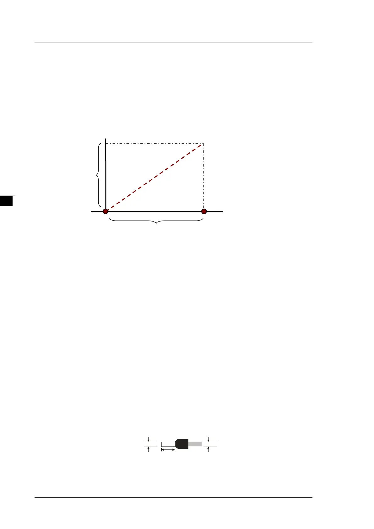
the analog range is -10 V to +10 V, the digital range is -10.0 to +10.0, the HSP scale is 10.0, and the LSP
scale is -10.0. The digital values -10.0 to +10.0 correspond to the analog values -10 V to +10 V, as the
example below shows.
4.2.6 Wiring
Precautions
To ensure the digital-to-analog module functions well and reliably, the external wiring must prevent noise.
(1) To prevent a surge and induction, the AC cable and the output signal cables that are connected to the
AS04DA-A must be separate cables.
(2) Do not install or bound the cable to a main circuit, a high-voltage cable, or a cable connected to a
load that is not a PLC.
(3) Ground shielded cables and hermetically sealed cables separately.
(4) Terminals with insulation sleeves cannot be arranged as a terminal block, so you should cover the
terminals with insulation tubes.
(5) Connect 24 to 22 AWG (1 mm) wires to the input/output terminals. The plastic jackets that are
removed from the cables should be 8 mm to 10 mm long. The specifications for the terminals and the
wiring of the terminals are shown below. Use only copper leads that can resist temperatures above
60° C /75° C.
(6) Note: use cables with the same length (less than 200 m) and use wire resistance of less than 100
ohm.