Chapter 9 Serial Communication Module AS00SCM
9- 15
9.3.3.2 Corresponding Input / Output Device Range
When the AS00SCM-A module acts as a CANopen slave, the CPU PLC assigns the input/output device ranges
according to the placement of the AS00SCM-A. The corresponding input/output device ranges from the right hand
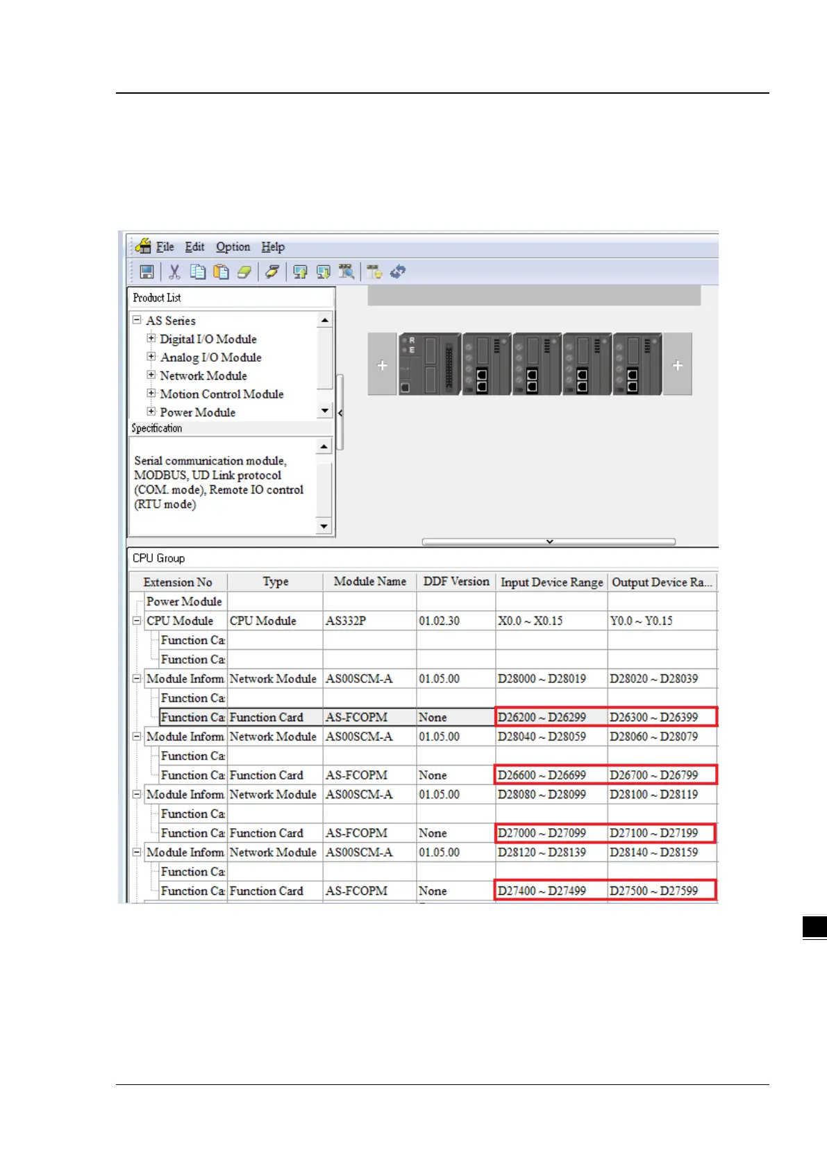
side of the CPU PLC are shown in the example below from the HWCONFIG utility. The red box below is the data
exchange section for AS00SCM-A, when the AS00SCM-A acting as a CANopen slave.