ASDA-B2-F Control Mode of Operation
September, 2015 6-27
6
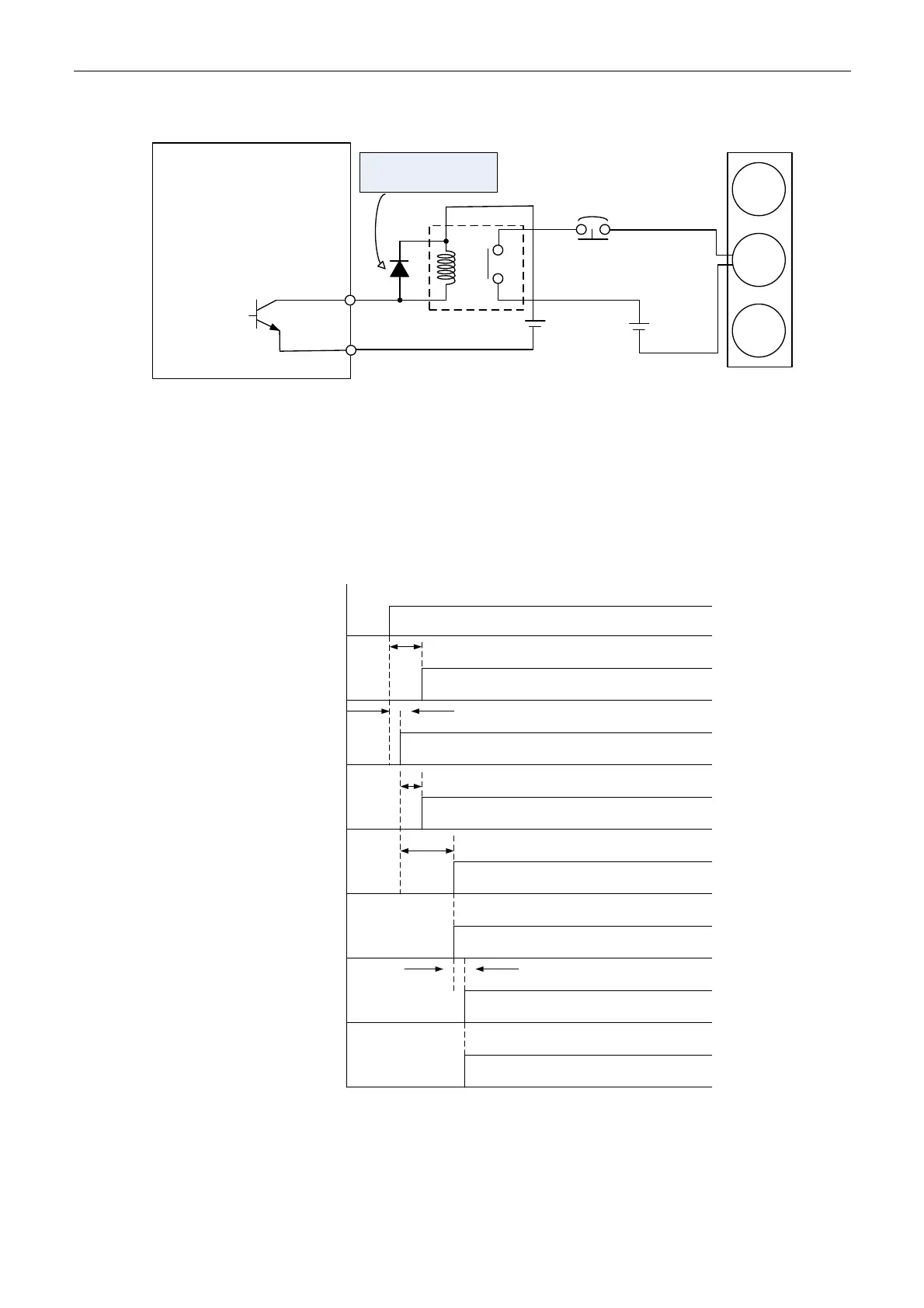
DOX-
Servo Drive
DOX+
DO1: (7,6)
DO2: (5,4)
DO3: (3,2)
DO4: (1,26)
DO5: (28,27)
DOX: (DOX+,DOX-)
X=1,2,3,4,5
Ensure the polarity of the
diode is correct, or it
might damage the drive
DC 24 V
Do not connect VDD-COM+
Relay
DC 24 V
For brake
When emergency stop signal is
activated, this circuit breaker will
be enabled
Brake 1 (Blue)
Brake 2 (Brown)
Motor
Brake
Encoder
Figure 6-15 Wiring of brake
Note:
1. Please refer to Chapter 3 for wiring.
2. The brake signal controls the solenoid valve, provides power to the brake and enables the brake.
3. Please note that there is no polarity in coil brake.
4. Do not use the same mains to provide brake power and the control power (VDD).
L1c, L2c
Control Power
5 V
Control Power
R, S, T
Main Power
BUS Voltage
READY
SERVO
READY
Servo On
(DI input)
Servo On
(DO output)
Position/Speed/
Torque
Command Input
1 sec
More than 0 msec
800 ms
2 sec
1 msec (min) + Delay Time
of Digital Filter (P2-09)
Input available
Figure 6-16 Timing Diagram of Control Power and Main Power

 Loading...


