Wiring ASDA-B2-F
3-26 September, 2015
3
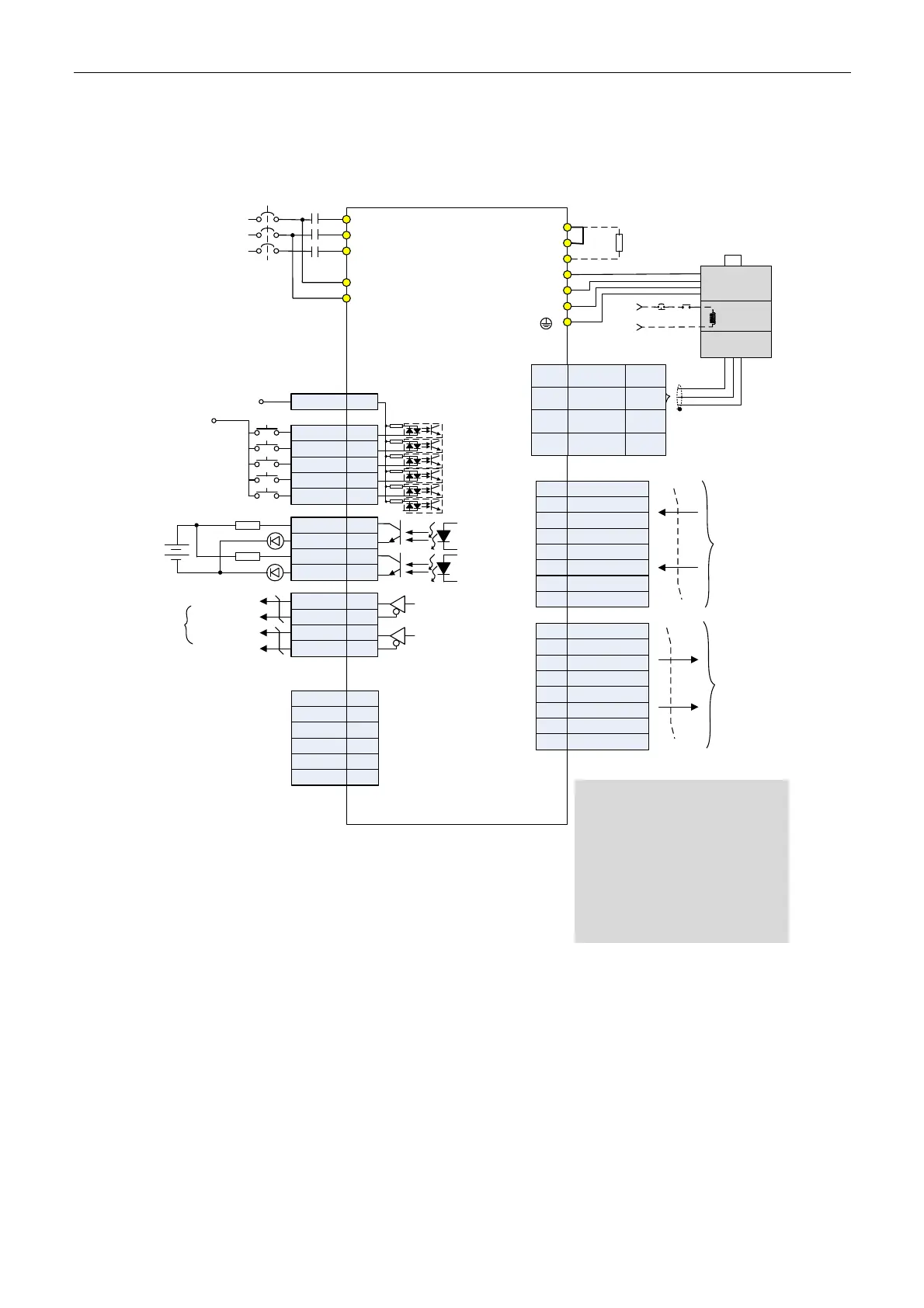
3.7 Standard Connection Example
Communication Mode
COM+
DI1
DI2
DI3
DI4
DI5
11
5
4
3
1
2
CN2
CN1
P
⊕
D
C
U
V
W
4.7KΩ
4.7KΩ
4.7KΩ
4.7KΩ
4.7KΩ
4.7KΩ
R
S
T
L1c
L2c
MC
MCCB
AC 200/230 V
Three-phase
50/60 Hz
Servo Drive
ASDA-B2-F series
Reserved
ORGP
NL
PL
EMGS
red
White
black
Green
SG
Brake
Power Supply
Encoder
BRKREMGS
24V
*1
*4
*2
*3
24V_GND
24V
DO1+
DO2-
DO2+
DO1-
1.5 KΩ
1.5 KΩ
SRDY
ZSPD
24V
15
14
12
13
/OA
OA
OB
/OB
A phase
differential signal
B Phase
differential signal
Encoder
pulse
output
9
10
8
7
RS232_RX
RS232_TX
GND
-
5
6
4
3
1
2
CN3
-
-
CN6 DMCNET
9
11
10
12
13
14
15
16
Data Output
DMCNET_1A
-
-
-
-
DMCNET_1B
DMCNET_2A
DMCNET_2B
1
3
2
4
5
6
7
8
Data Input
DMCNET_1A
-
-
-
-
DMCNET_1B
DMCNET_2A
DMCNET_2B
T+
T-
+5V
GND
5
6,7
8
4
blue
Blue/
black
Red/
Red&White
Black/
Black&
White
Regenerative
Resistor
Twisted- pair
or twisted-
shield cable
Note:
*1 Please refer to Chapter 3.3.3 for
C3 ~ C6 wiring diagrams (SINK/
SOURCE mode).
*2 Models below 200 W have no
built-in braking resistor.
*3 The coil of brake has no polarity.
*4 Single-phase connections are for
servo drives 1.5 kW and below only.

 Loading...


