ASDA-B2-F Wiring
September, 2015 3-15
3
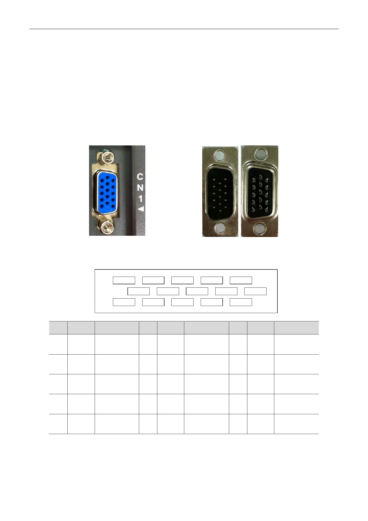
3.3 I / O Signal (CN1) Connection
3.3.1 I / O Signal (CN1) Connector Terminal Layout
In order to have a more flexible communication with the master (the host controller), 2
programmable Digital Outputs (DO) and 5 programmable digital inputs (DI) are provided. The
setting of 5 digital inputs and 2 digital outputs of each axis are parameter P2-10 ~ P2-14 and
parameter P2-18 ~ P2-19 respectively. In addition, the differential output encoder signal, A+, A-,
B+, and B- are also provided. The followings are the pin diagrams.
CN1 Connector (female)
Connector (male)
Front View Rear View
DO1-DO2-
1
DO2+ DO1+
COM+
DI2-DI3-DI4- DI1-DI5-
GND/OB OA/OAOB
5
10
15 11
6
Pin
No
Name Function
Pin
No
Name Function
Pin
No
Name Function
1 DI1- Digital input 6 GND
Control Panel
Power 0 V
11 COM+
Power ground
(12 ~ 24 V)
2 DI2- Digital input 7 OA
Encoder A
pulse output
12 DO1+ Digital output
3 DI3- Digital input 8 /OA
Encoder /A
pulse output
13 DO1- Digital output
4 DI4- Digital input 9 OB
Encoder B
pulse output
14 DO2+ Digital output
5 DI5- Digital input 10 /OB
Encoder /B
pulse output
15 DO2- Digital output

 Loading...


