ASDA-B2-F Communications
September, 2015 8-5
8
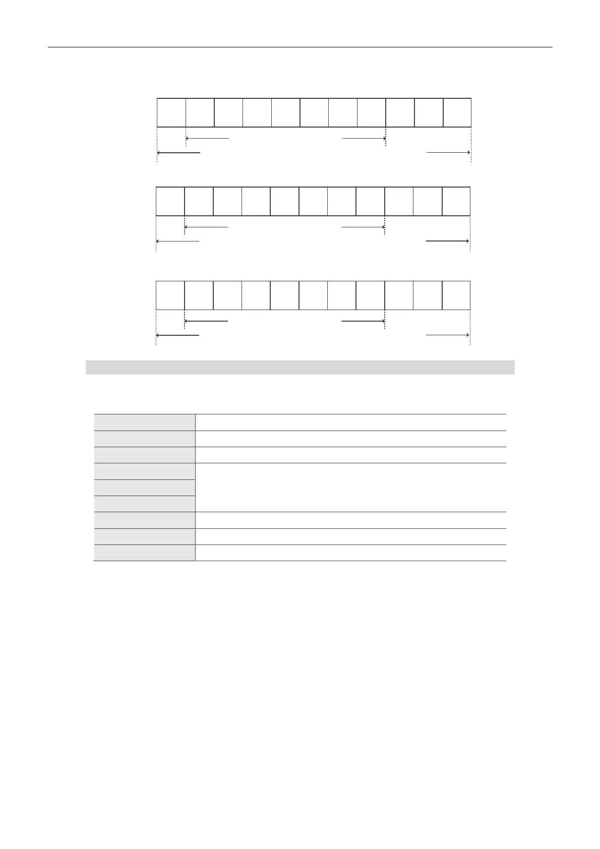
11-bit character frame (for 8-bit character)
8N2
Start
bit
7
Stop
bit
0123456
8-data bits
11-bit character frame
L H
Stop
bit
8E1
Start
bit
7
Stop
bit
0123456
8-data bits
11-bit character frame
L H
Even
parity
8O1
Start
bit
7
Stop
bit
0123456
8-data bits
11-bit character frame
L H
Odd
parity
Communication Data Structure
Definitions of data frame for ASCII and RTU mode are as below:
ASCII Mode:
Start Start character ‟:” (3AH)
Slave Address Communication address: 1 byte consists of 2 ASCII codes
Function Function code: 1 byte consists of 2 ASCII codes
Data (n-1)
Data content: n word = n x 2 byte = consists of n x 4 ASCII codes, n<=10 …….
Data (0)
LRC Error check: 1 byte consists of 2 ASCII codes
End 1 End code 1: (0DH)(CR)
End 0 End code 0: (0AH)(LF)
The start character of communication in ASCII mode is colon ‟:” (ASCII code: 3AH). Slave
address is constituted by two characters in ASCII code. The end code is CR (Carriage Return)
and LF (Line Feed). The communication address, function code, data content and error checking
LRC (Longitudinal Redundancy Check), etc. are between the start character and end code.

 Loading...


