ASDA-B2-F Wiring
September, 2015 3-17
3
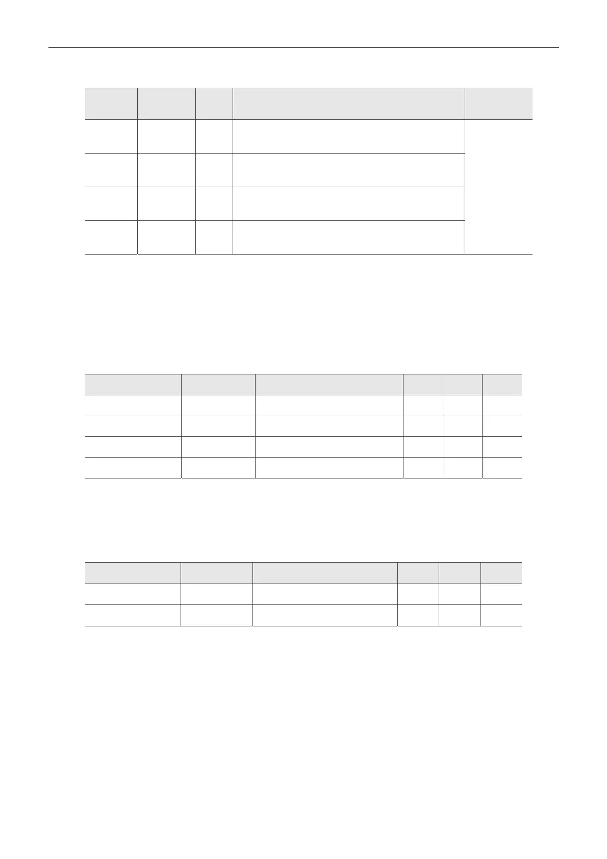
The explanation of DI signal default setting is as the following.
DI Signal
Name
Operation
Mode
Pin No Function
Wiring Method
(Refer to 3.3.3)
ARST ALL -
When the alarm (ALRM) occurs, this signal is used to
reset the servo drive and enable DI.SRDY again.
C3,C4
EMGS ALL 5
It is contact B and always has to be ON; otherwise the
alarm (ALRM) will occur.
NL
(CWL)
ALL 3
Reverse inhibit limit (contact B) and always has to be
ON; or the alarm (ALRM) will occur.
PL
(CCWL)
ALL 4
Forward inhibit limit (contact B) and always has to be
ON; or the alarm (ALRM) will occur.
The default setting of DI and DO in each operation mode is shown as the followings. The table
below is presented in a different way and the corresponding operation mode is put in the table in
order to avoid confusion.
Table 3.1
Default Value of DI Input Function
Symbol DI code Input Function DMC Sz Tz
ARST 0x02 Alarm reset DI5 DI5 DI5
EMGS 0x21 Emergency stop DI5 DI5 DI5
NL(CWL) 0x22 Reverse inhibit limit DI3 DI3 DI3
PL(CCWL) 0x23 Forward inhibit limit DI4 DI4 DI4
Note:
Please refer to Section 3.3.1 for corresponding pin from DI 1 ~ 5.
Table 3.2 Default Value of DO Input Function
Symbol DO code Input Function DMC Sz Tz
SRDY 0x01 Servo ready DO1 DO1 DO1
ZSPD 0x03 Zero-speed reached DO2 DO2 DO2
Note:
Please refer to Section 3.3.1 for corresponding pin from DO1 ~ 2.

 Loading...


