Panel Display and Operation ASDA-B2-F
4-8 September, 2015
4
P0-02
Setting
Value
Monitor Displayed
Symbol
Description Unit
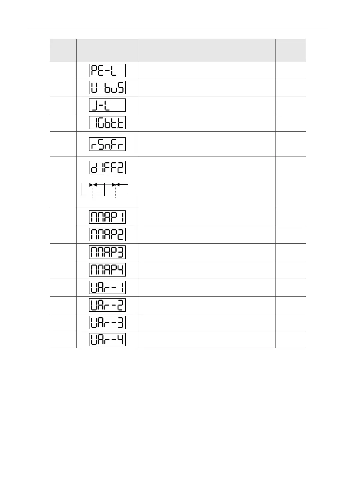
13
Peak torque [%]
14
Main circuit voltage [Volt]
15
Load / Motor inertia ratio (Note: If it shows 13.0, it
means the actual inertia is 13)
[1 times]
16
IGBT temperature
[°C]
17
Resonance frequency (Low byte is the first resonance
and high byte is the second one).
[Hz]
18
The absolute pulse number of encoder Z phase equals
the homing value, 0. It will be +5000 or -5000 pulse
when rotating in forward or reverse direction.
-
19
Mapping parameter #1: shows the content of parameter
P0-25 (specify the mapping target by P0-35)
-
20
Mapping parameter #2: shows the content of parameter
P0-26 (specify the mapping target by P0-36)
-
21
Mapping parameter #3: shows the content of parameter
P0-27 (specify the mapping target by P0-37)
-
22
Monitor variable #4: shows the content of parameter
P0-28 (specify the monitor variable code by P0-38)
-
23
Monitor variable #1: shows the content of parameter
P0-09 (specify the monitor variable code by P0-17)
-
24
Monitor variable #2: shows the content of parameter
P0-10 (specify the monitor variable code by P0-18)
-
25
Monitor variable #3: shows the content of parameter
P0-11 (specify the monitor variable code by P0-19)
-
26
Monitor variable #4: shows the content of parameter
P0-12 (specify the monitor variable code by P0-20)
-
Z
Z
Z
0
+5000,
0
+5000,
0

 Loading...


