Chapter 16 PLC Function ApplicationsC2000
16-22
Commonly used control circuits
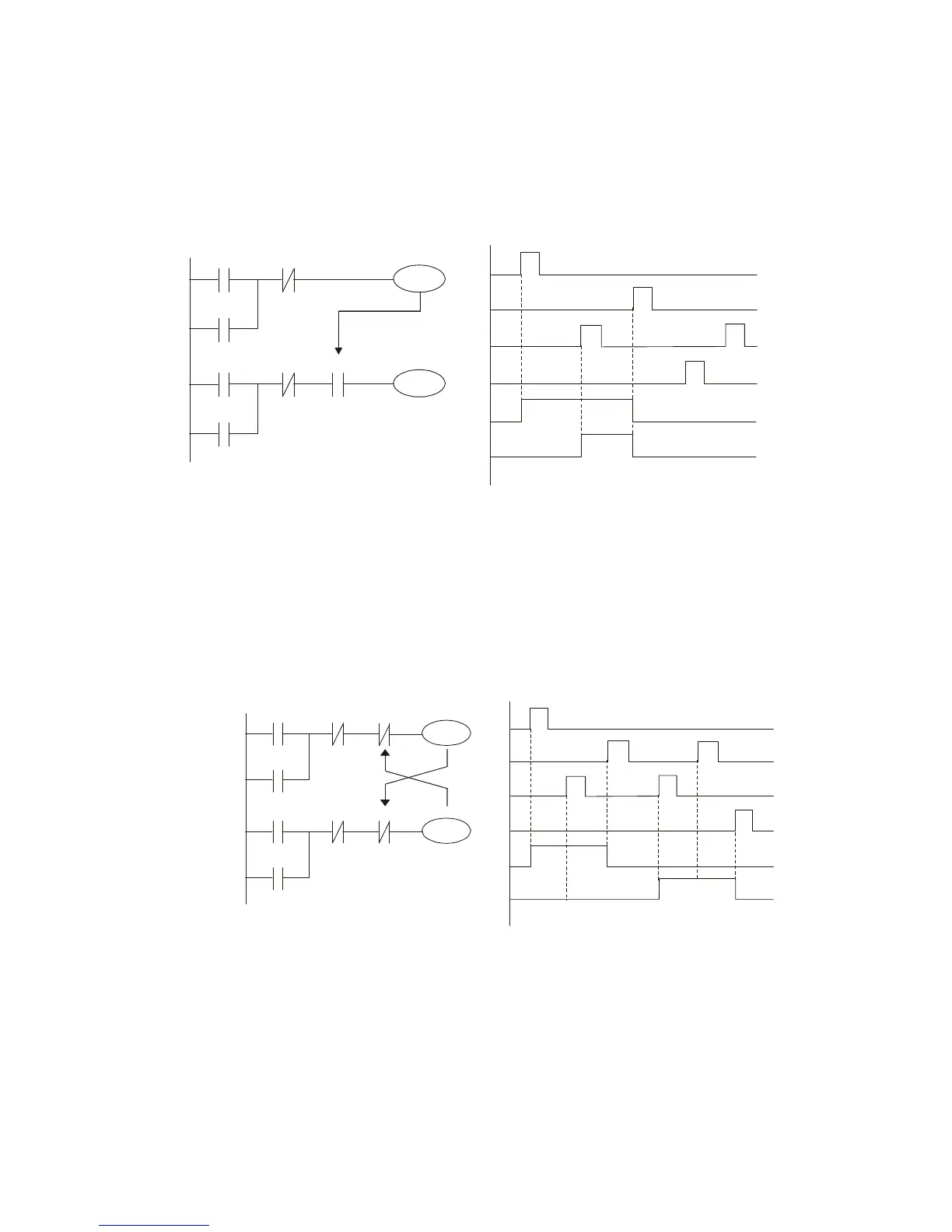
Example 4: Conditional control
X1, X3 are respectively start/ stop Y1, and X2 & X4 are respectively start/ stop Y2; all have
protective circuits. Because Y1's NO contact is in series with Y2's circuit, it becomes an
AND condition for the actuation of Y2. The action of Y1 is therefore a condition for the action
of Y2, and Y1 must be actuated before Y2 can be actuated.
X1
X3
Y1
Y1
X2
X4
Y2
Y2
Y1
X1
X3
X2
X4
Y1
Y2
Example 5: Interlocking control
The figure below shows an interlocking control circuit. Depending on which of the start
contacts X1, X2 is valid first, the corresponding output Y1 or Y2 will be actuated, and when
one is actuated, the other will not be actuated. This implies that Y1 and Y2 cannot be
actuated at the same time (interlocking effect). Even if both X1 and X2 are valid at the same
time, because the ladder diagram program is scanned from the top down, it is impossible for
Y1 and Y2 to be actuated at same time. This ladder diagram assigns priority only to Y1.
X1
X3
Y1
Y1
X2
X4
Y2
Y2
Y1
X1
X3
X2
X4
Y1
Y2
Y2
 Loading...


