Chapter 7 Optional AccessoriesC2000
7-46
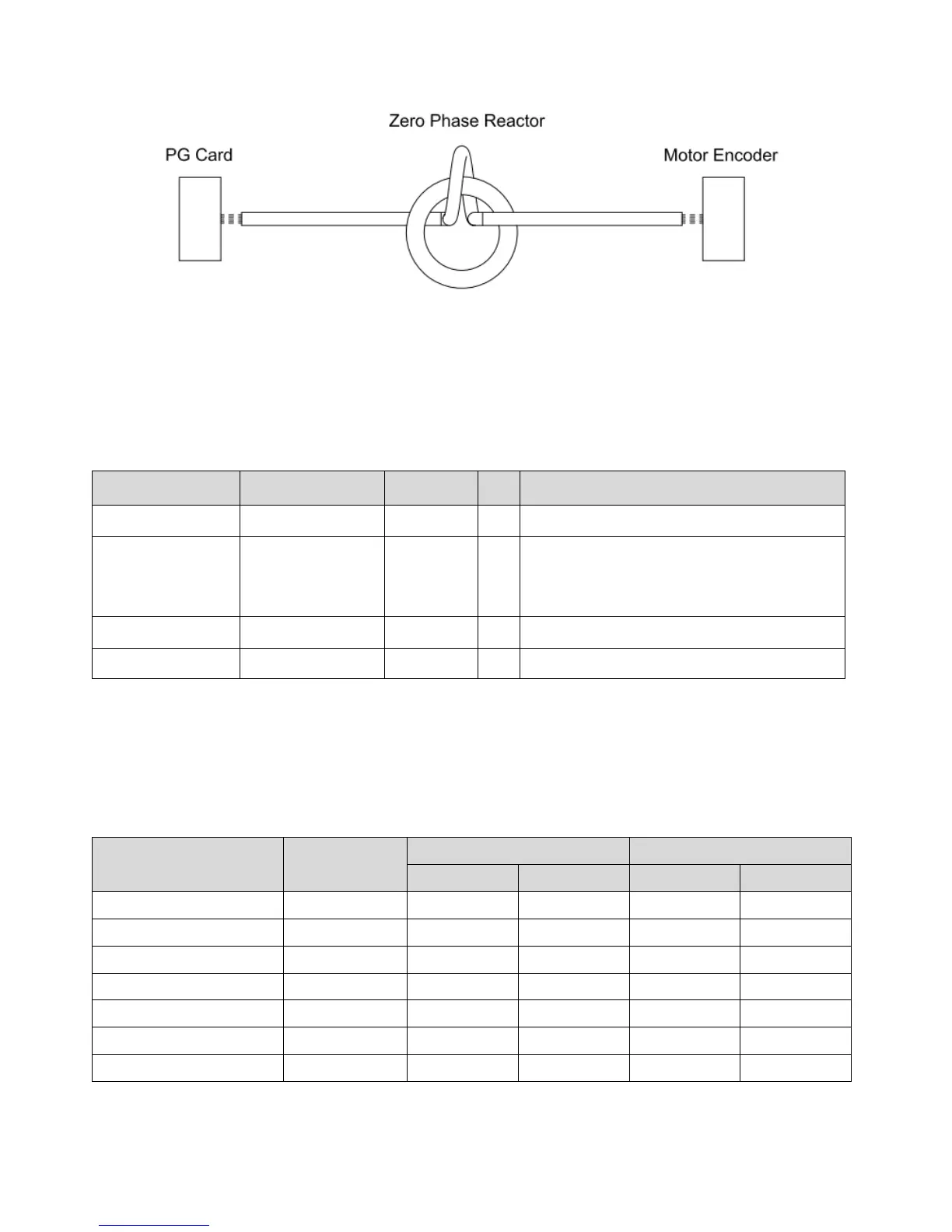
Diagram E
Note 1: The table above gives approximate wire size for the zero phase reactors but the selection is ultimately
governed by the type and diameter of cable fitted, i.e. the cable must fit through the center hole of zero phase
reactors.
Note 2: Only the phase conductors should pass through, not the earth core or screen.
Note 3: For the zero phase reactor used for signal cables, it is recommended to install near to the driver and well
fixed, as to prevent vibration and pulling of the cable.
Model*
Recommended wire
size
Wiring
method
Q’ty Applicable cables
T60006L2050W565
≦1 AWG
Diagram D 1 D-sub
T60006L2040W453
≦8 AWG
Diagram C 1
Category 5e shielding、Shielded twisted pair
cable、CAN standard cable
(TAP-CB05, TAP-CB10)
T60004L2025W622
≦10AWG
Diagram E 1 PG card signal cable
T60004L2016W620
≦12AWG
Diagram E 1
PG card signal cable
Note 1: *The table above is for reference only, please choose the zero phase reactor based on the actual
wire size that you are using.
Note 2: Some of the cables are recommended to choose bigger zero phase reactor due to its corresponded
mechanical size.
Recommended max. motor wire size of zero phase reactor (included LUG width and temp. tolerance of motor cable)
Zero phase reactor
Available max. wire
size/ LUG width
Available max. AGW (1C*3) Available max. AWG (4C*1)
75C 90C 75C 90C
RF008X00A 13MM 3AWG 1AWG 3AWG 1AWG
RF004X00A 16MM 1AWG 2/0AWG 1AWG 1/0AWG
RF002X00A 36MM 600MCM 600MCM 1AWG 1/0AWG
RF300X00A 73MM 650MCM 650MCM 300MCM 300MCM
T60006L2040W453 11MM 9AWG 4AWG 6AWG 6AWG
T60006L2050W565 16MM 1AWG 2/0AWG 1AWG 1/0AWG
T60006L2160V066 57MM 600MCM 600MCM 300MCM 300MCM
Table 7-54
Table 7-55