9 Application Instructions API 150-199
DVP-PLC Application Manual
9-5
5. After receiving the data sent back from AC motor drive is completed, PLC will auto-check if the received data
are incorrect. M1140 will be On if there is an error.
6. If the device address is illegal to a designated communication device, the communication device will respond
with an error message and PLC will store the error code in D1130 and M1141 = On. For example, if 8000H is
illegal to VFD-S, M1141 will be On and D1130 = 2. See user manual of VFD-S for error codes.
7. After M1140 = On or M1141 = On, PLC will send another correct datum to AC motor drive. If the data sent back
from AC motor drive is correct, M1140 and M1141 will be reset.
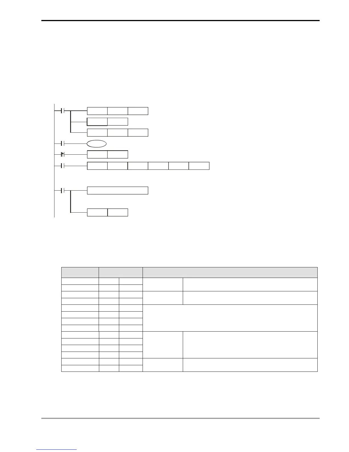
H87
MOV
M1002
D1120
SET
M1120
K100
MOV
D1129
M1127
RST
M1127
M1143
X10
Set up communication
protocol 9600, 8, E, 1
Retain communication protocol
Communication
time-out 100ms
MODRW
K6
K1
X0
H2000
D50
K1
Address of
communi-
cation
device K1
Function
code K6:
write 1
word datum
Data address
H2000
Register
for storing
the data
Data length
(word)
SET
X0
M1122
Set up sending request
Process of received data
ASCII mode: the received data will be stored in special registers D1070 ~ D1076 in ASCII format.
Sending/receiving of data is completed. The flag is reset.
RTU mode: the received data will be stored in special registers D1070 ~ D1077 in hex format.
8. ASCII Mode: When PLC is connected to VFD-S AC motor drive.
PLC Ö VFD-S, PLC sends: “01 06 0100 1770 71”
VFD-S Ö PLC, PLC receives: “01 06 0100 1770 71”
Registers for sent data (sending messages)
Register DATA Explanation
D1256 Low ‘0’ 30 H ADR 1
D1256 High ‘1’ 31 H ADR 0
Address of AC motor drive: ADR (1,0)
D1257 Low ‘0’ 30 H CMD 1
D1257 High ‘6’ 36 H CMD 0
Instruction code: CMD (1,0)
D1258 Low ‘0’ 30 H
D1258 High ‘1’ 31 H
D1259 Low ‘0’ 30 H
D1259 High ‘0’ 30 H
Data Address
D1260 Low ‘1’ 31 H
D1260 High ‘7’ 37 H
D1261 Low ‘7’ 37 H
D1261 High ‘0’ 30 H
Data content The content of register D50 (H1770 = K6,000)
D1262 Low ‘7’ 37 H LRC CHK 1
D1262 High ‘1’ 31 H LRC CHK 0
LRC CHK (0,1) is error check