9 Electrical CAM
DVP-PM Application Manual
9-12
Control steps:
Step 1: Initialization
(1) Clear the content in registers D1848, D1849, D1862, D1863, D1868.
(2) Set up input pulse type as A/B phase (D1864 = H200)
(3) Set up pulse output type of Y axis as A/B phase (H30)
(4)
Set up D1799 (input terminal polarity setting) = 6. MPGA/MPGB are NO contacts
(5) Set up operation speed of Y axis variable speed operation (in this case Y axis outputs signals
as input signals of Master).
(6) Set up lower bound of CAM sync output D1839, D1838 = 20000 and upper bound D1843,
D1842 = 30000. Between Master position 20000~30000 (can be monitored by D1862), CLR0
is ON. However, the CLR LED on the MPU will not respond to it. To monitor CLR signal, you
can connect CLR0- with 0V and CLR0+ with Xn input contact then monitor the ON/OFF status
of Xn input.
Step 2: Set On M0 to enable cyclic E-CAM.
When M0 is rising-edge triggered, Master starts to receive the variable speed pulses from Y
axis, and Slave operates according to the above E-CAM Data curve. In addition, CLR0 = ON
during Master position 20000~30000.
Step 3: Reset M0.
When M0 is falling-edge triggered, E-CAM stops.
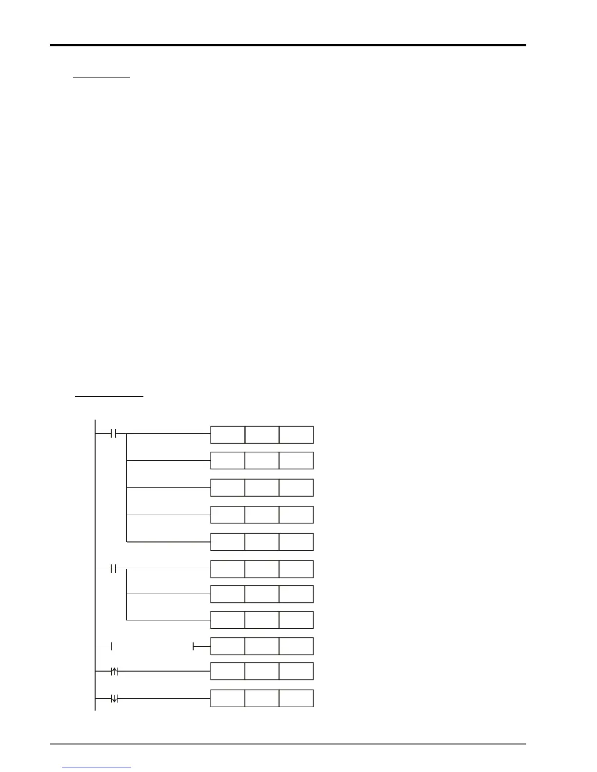
Ladder Diagram:
DMOV K5000 D1920
M1002
ZRST D1860 D1863
M1002
DMOV K20000 D1838
DMOV
K30000
D1842
MOV
H10 D1926
MOV H2000 D1846
ZRST D1848 D1849
Set up pulse input type
as A/B phase
Set up D1799 (input terminal polarity setting)= 6.
MPGA0/MPGB0 are NO contacts.
Set up operation speed of Y axis
variable speed operation
MOV H200 D1864
MOV H30 D1896
MOV K6 D1799
MOV H0 D1846
M0
M0
LD= D1846 H2000
Lower bound of E-CAM sync output
Upper bound of E-CAM sync output
When D1846=H2000, Y axis variable speed
operation executes.
When M0 is rising-edge triggered, set
D1846=H2000 to enable cyclic E-CAM
When M0 is falling-edge triggered, cyclic E-CAM
stops.
 Loading...


